
Nine parents out of ten pay attention to strollers’ comfort and safety and, concerning this, Bosch has ideated a new system that marks its entry in a new market.
In the wind tunnel, with 7-degree intensity according to Beaufort scale, the air hits the stroller at a speed of 60 km/h and strongly shakes the canopy, but the stroller does not move thanks to the new e-stroller system by Bosch. It is much more than an electric traction, it is a stroller assistant with a complete range of comfort and safety functions. Besides the thrust support and the automated braking function, this system is in fact provided with an alarm function, with a series of highly technological sensors and the possibility of connecting it to the smartphone through an app.
The traction system includes two silent electric motors on the rear axle, a Bluetooth module and a system of smart sensors. These sensors, used also in smartphones, measure also the stroller’s speed and acceleration, detecting also the type of surface travelled.
“Baby electric motors”, strollers with e-stroller system

Energy storage for the electric car. Dry electrode coating technology

Researchers at the Fraunhofer Institute for Material and Beam Technology IWS in Dresden have developed a new production process with the aim of efficient and environmentally friendly future battery production. They coat the electrodes of the energy storage cells with a dry film instead of liquid chemicals. This simplified process saves energy and eliminates toxic solvents. A Finnish company is currently successfully testing the new IWS technology in practice.
Better and more cost-efficient production methods for energy storage are increasingly in demand, especially in Germany: all major automobile manufacturers have launched ambitious electric vehicle programs that will ensure a sharp rise in demand for batteries. So far, German companies have been purchasing the cells for this purpose in Asia.
There are two main reasons driving this trend: Asian technology groups have many years of experience in the mass production of battery cells and a lot of energy is consumed in these processes. Production at locations with high electricity prices, such as Germany, is, therefore, very high-cost.
No more toxic solvents – lower electricity costs
It is exactly this fact the Saxon Fraunhofer engineers want to change: “Our dry transfer coating process aims to noticeably reduce the process costs in electrode coating,” emphasizes IWS project manager Dr. Benjamin Schumm. “Manufacturers can eliminate toxic and expensive solvents and save energy costs during drying. In addition, our technology also facilitates the use of electrode materials that are difficult or even impossible to process wet-chemically.”
But exactly these materials are needed for future batteries with higher energy density. “For all these reasons, we think that our technology can help to achieve internationally competitive battery cell production in Germany and Europe.”
Pilot plant successfully started in Finland
This potential is also seen by Fraunhofer’s Nordic partners: The Finnish battery company “BroadBit Batteries”, together with IWS, has commissioned a pilot plant in its Espoo factory, which coats electrodes with dry electrode material instead of wet pastes, as has been common in industry up to now. BroadBit uses it to produce new types of sodium ion batteries. “The demand for our technology is high, even in Germany,” reports Benjamin Schumm. On a laboratory scale, the IWS can already coat electrode foil with a remarkable production speed of several meters per minute. In this respect the Dresden engineers can show the potential for transferring the technology to the production scale.
Limits of classic wet chemistry until now, cell producers have mostly coated their battery electrodes in a complex wet-chemical process. First, they mix the active materials, intended later to release the stored energy, with additives to create a paste. In this process they add organic solvents, which are expensive and usually toxic. In order to protect operators and the environment, elaborate precautions for occupational safety and reprocessing are necessary. Once the paste has been applied to thin metal foils, a further expensive process step begins: Dozens of meter long heating sections dry the coated films before they can be further processed. This drying procedure usually causes high electricity costs”.
Binding molecules form a cobweb
The new film transfer technology for dry electrode coating, on the other hand, operates without these ecologically damaging and expensive process steps: the IWS engineers mix their active material with binding polymers. They process this dry mixture in a rolling mill known as “calender”.
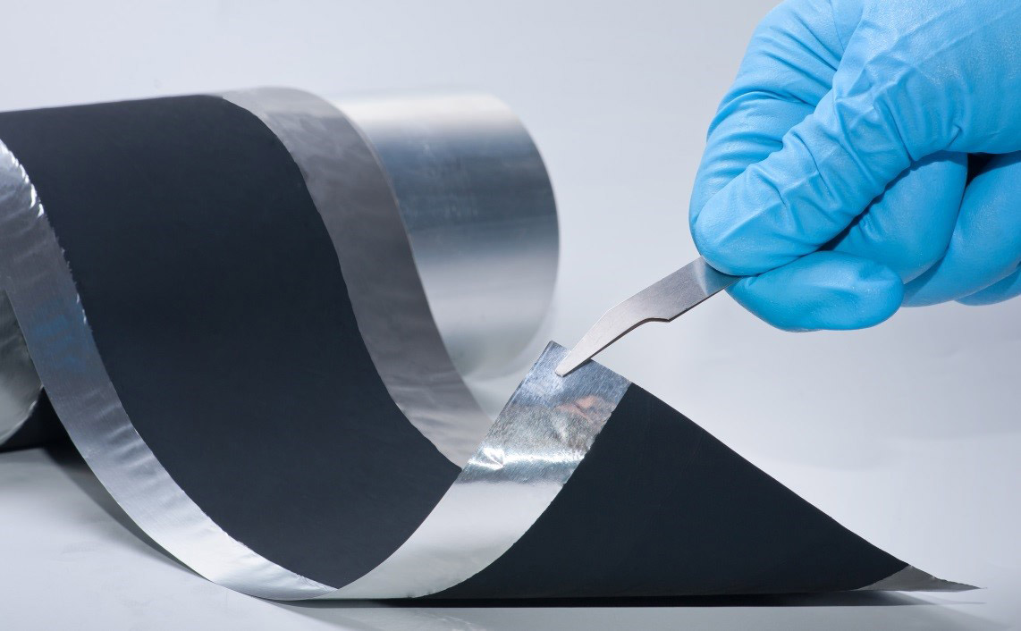
The shear forces in this system tear entire molecular chains out of the binder polymers. These “fibrils” join with the electrode particles as in a spider web. This provides the electrode material with stability. The result is a flexible dry electrode material layer. In the next step, the calender laminates the 100 micrometer thick film directly onto an aluminum foil, thus creating the battery electrode.
On the way to the solid state fireproof battery
“In this way, we are also able to process materials for new battery generations where classical processes fail,” says Benjamin Schumm. These include, for example, energy storage systems that use sulfur as active material or solid-state batteries which employ ion-conducting solids instead of flammable liquid electrolytes. “These batteries will be able to store more energy in the same volume than today’s lithium-ion batteries,” says the IWS scientist with a view to the future.
“However, these solid electrolytes can lose their functional properties in contact with solvents. A solvent-free coating process is significantly better qualified to produce these storage media.” On the way of processing electrodes for all solid state batteries the researchers have reached one important milestone by applying their dry film technology using extremely low binder contents.
Process could replace classic paste processes
The Dresden engineers now aim at enhancing their technology in cooperation with industrial partners in order achieve its breakthrough. In the BMBF-funded “DryProTex” project, for example, they are further developing the dry transfer coating process together with the companies Saueressig, INDEV, Netzsch Trockenmahltechnik and Broad-Bit Batteries. The partners expect a fundamental change in battery production: “The technology offers great potential to replace conventional processes for paste-based electrode production on the long run,” concludes Benjamin Schumm. In the DryProTex project material, process and equipment developments are conducted with the aim of realizing process design for industrial scale dry cathode production.
To know more about this Research visit Fraunhofer web site>>>
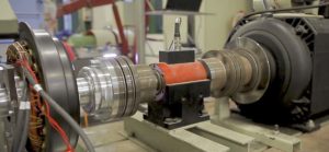
Test benches for engineering students to asses industrial electronic equipment

The University of Southern Denmark gives young engineering students an opportunity to be part of developing the green technology of the future in a creative study environment with modern teaching facilities and dedicated teachers.
The engineering students are taught electronics and challenged with real-life industrial equipment driven by electric motors and drives manufactured by Nidec.
As part of the teaching projects, the institute and the students have access to several advanced electronic test benches, which gives them a good insight into the handling, testing and research of different combinations of industrial electronic equipment and teaches them to test torque, speed, load, etc. under realistic conditions.
The test benches use Nidec Leroy-Somer motor units (servo motors, LSMV and IMfinity induction ranges) and Control Techniques Unidrive M600/M700 drives and combine different set-ups of advanced variable speed drives and high-tech electric motors, which have the flexibility to test a wide variety of electronic equipment.
Each semester, the electronic engineering degree programme includes project work on a current topic, for example how to design the electronic controller of an electric go-kart motor.
In connection with the project, the students have access to a genuine go-kart with an electric motor as well as a corresponding test bench with programmable drives and electric motors.
Non-conventional design of concentrated windings

Thanks to appropriate numerical optimisation techniques, it is possible to drastically reduce the losses that originate in permanent magnets due to eddy currents, with a small reduction in the torque that can be developed by the machine. In the same way, it is possible to design machines with concentrated windings with combinations of number of slots and poles traditionally considered incompatible or not feasible in symmetrical form. This is confirmed by the studies carried out by Professor Alberto Tessarolo, University of Trieste, and by examples of how this approach can be of great application interest.
by Gianandrea Mazzola in collaboration with Professor Alberto Tessarolo,
University of Trieste

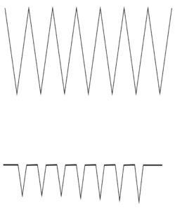
In the construction technology of modern electrical machines, the use of so-called “concentrated” or “wound tooth” stator windings is becoming more and more frequent, replacing, where possible, the more traditional “distributed” windings. The difference between the two types of windings can be appreciated by the examples shown in figure 1. It will be observed that the distributed winding consists of “ample” coils which embrace a relatively large portion and connect leads arranged in “distant” slots (figure 1a). Conversely, concentrated windings consist of “tooth coils”, i.e. coils each wound around a tooth in the stator’s magnetic core (figure 1b and figure 1c).


A drawback of concentrated windings is the fact that they, even when supplied with ideal currents, produce harmonic fields at the machine air gap which are capable of inducing losses due to eddy currents in permanent magnets and consequent overheating.
Moreover, it is not always possible to opt for concentrated windings. This is possible, in fact, at the state of the art, only for motors and permanent magnet generators in which the number of slots, indicated by Z, is similar (a little higher or a little lower) to the number of poles P.
In general, concentrated windings are usually considered feasible only if the number of slots Z and the number of poles P satisfy a precise algebraic relationship. More precisely, for the feasibility of winding, the quantity K, as shown in the following relation:
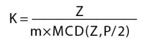
must be an integer number, having indicated by MCD (Z, P/2) the Maximum Common Divisor between Z and P/2. The above relation restricts the choice of the number of slots Z and poles P to a limited number of combinations (which we can define as “conventional combinations”). The limitation in question becomes particularly restrictive in the case of windings with more than three phases (m>3), as is often required to increase reliability. In the case of multi-phase windings, the scope of permissible poly-slot combinations is significantly reduced, thus significantly limiting the designer’s choice and precluding, in some cases, the adoption of wound tooth technology.
Large reduction of losses in the magnets, with small reduction in torque
In response to these critical issues, Professor Tessarolo has recently developed and proposed a methodology for the optimized design of concentrated windings, using multi-layer configurations.
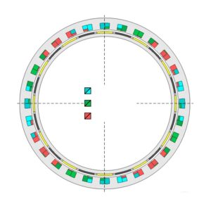
“Configurations in which – explains Professor Tessarolo – there can be several coils of different phases wound around the same tooth, as exemplified in figure 2, identifiable by different colours depending on the phase to which they belong.
The methodology, which is based on a particular algorithm of quadratic optimization, nevertheless easily implemented in widespread computing environments (such as Matlab), permits reducing some of the drawbacks of concentrated winding machines.
“In particular – observes Professor Tessarolo – this methodology makes it possible to reduce the risk of overheating of the magnets due to harmonic fields at the air gap and the problem of the limited number of combinations of project-acceptable poly-slots, especially in the case of a number of phases greater than 3.
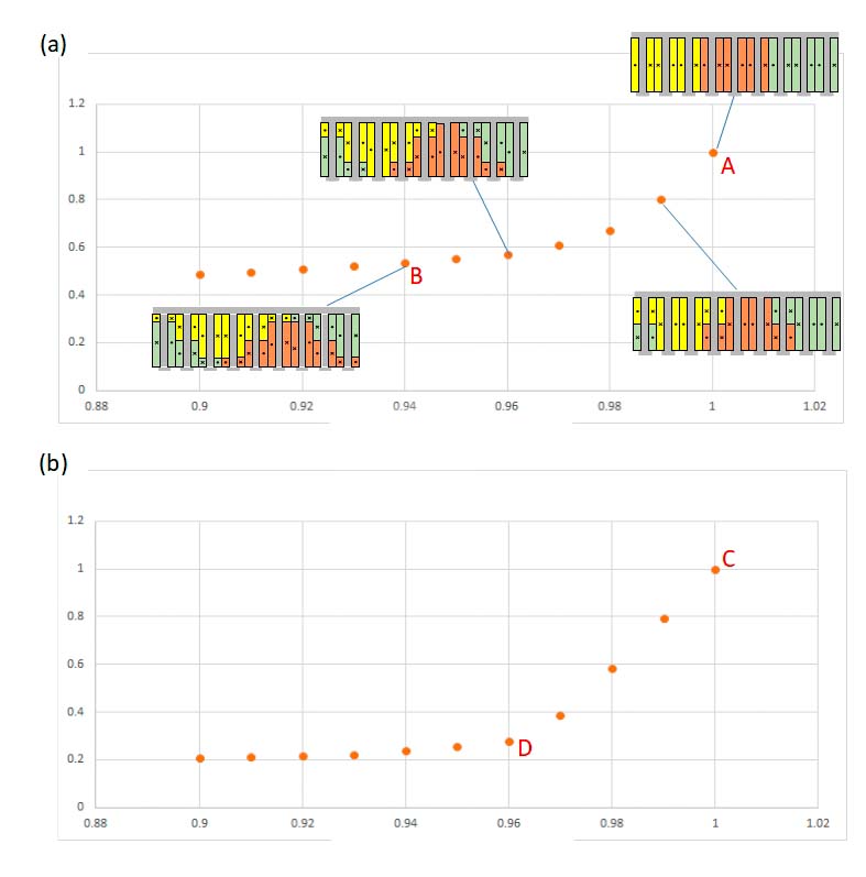
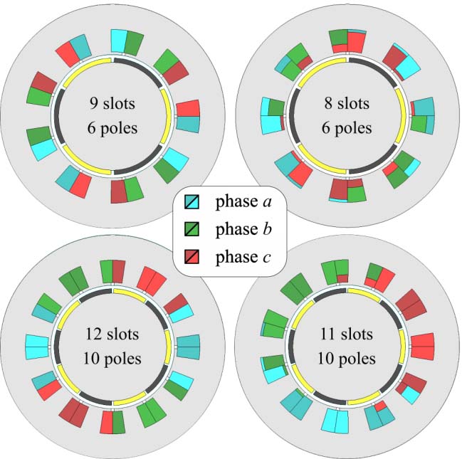
With regard to the reduction of ohmic losses in magnets, a multi-layer configuration optimized for wound tooth winding makes it possible to reduce the losses in magnets by up to 50%, at the price of a relatively limited reduction in the power developed by the machine. The potential for design optimization is exemplified in figure 3 for the combinations of 9 slots-8 poles and 12 slots-10 poles. The torque and losses of the magnets are normalized with respect to the value they assume for the traditional configuration (with a single coil for each tooth), represented by points A and C. Each point represents an optimized multi-layer design configuration.
“For example, in configuration B for the 9/8 machine, losses are reduced by about 50% at the expense of a 6% reduction in the nominal torque,” says Professor Tessarolo. “In the D configuration for the 12/10 machine, the losses in the magnets can be reduced by about 70% at the price of a drop of only 4% in the nominal torque.”
The optimization also extends the field of acceptable poly-slot combinations
The proposed optimisation method also permits extending the range of possible poly-slot combinations.
“In other words – underlines Professor Tessarolo – the method provides a symmetrical multi-layer configuration for a concentrated winding with a generic number of Z slots and P poles, even if Z and P are not such as to give a whole K in the above-mentioned equation”.
For example, figure 4 shows the cross-section of an 8-slot, 6-pole (unconventional) machine compared to the conventional 9-slot, 6-pole machine; similarly, the cross-section of an 11-slot, 10-pole (unconventional) machine is compared to the conventional 12-slot, 10-pole machine.
“From the comparison between conventional and non-conventional configurations – says Professor Tessarolo – it appears that the latter, in the face of a greater construction complication, in some cases show better performance. For example, the 9-slot and 6-pole machine in figure 4 has a high torque ripple which is about double that of the 8-slot and 6-pole machine. Or, to quote another example, the 11-slot and 10-pole machine has permanent-magnet losses around half those of the 12-slot and 10-pole machine”.
To give a more complete idea, the tables in figure 5 show a comparison between conventional (white cells) and non-conventional (grey cells) configurations in terms of winding factor and specific losses produced in the permanent magnets. It can be observed that some unconventional configurations have interesting and competitive values.

Operating benefits also for multi-phase machines
The possibility of using unconventional configurations can be particularly useful when designing multi-phase machines or machines consisting of several three-phase windings. This circumstance often occurs in applications that require continuity of service even in the event of a fault.
“For example – comments Professor Tessarolo – if you wanted to build a 12-phase machine, or with double three-phase winding, with eight poles, the conventional rules available in literature would force you to choose, to obtain a whole K from the above-mentioned report, a minimum number of 24 slots. It is clear that, for small machines, the use of Z equal to 24 could lead to unacceptable slot dimensions. The use of an optimized and unconventional multi-layer configuration can, in this case, be of help, making it possible to create a three-phase 8-pole, 9-slot double triad machine, as shown in figure 2”.
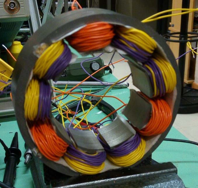
The prototype of this machine was also tested, recording the vacuum induced electromotive forces and then verifying the perfect electrical symmetry of the 9-phase winding, as shown in figure 6.
A further example of application is the 12-phase motor shown in figure 7, consisting of four three-phase windings offset by 90 degrees, each characterized by 7 slots and 6 poles. The choice of an unconventional winding in the case of what is shown in figure 7, was dictated by the need to have (for the maximum frequency allowed and the nominal speed) a total number of 24 poles, to be divided between the 4 independent units, of which the machine must consist for fault tolerance reasons. This resulted, for each unit, in a maximum number of 6 poles.
“The choice of 2 and 4 poles – underlines Professor Tessaroli – was not possible, as it led to excessive stator and rotor yoke thicknesses, such as to exceed the design dimensional constraints imposed on the radial dimensions. In this case, the project concerned the development of an electric outboard motor with integrated propeller, where space constraints were predominant. The number of poles for each unit was therefore fixed at 6, the choice of the number of slots such as to give an acceptable winding factor was between Z=9, Z=8 and Z=5, as shown in figure 5”.
The first (conventional) one was rejected because the torque ripple was too high. The only remaining options were therefore unconventional, i.e. 8 slots and 6 poles or 7 slots and 6 poles. The second was chosen because of its lower magnet losses and the almost zero torque ripple.
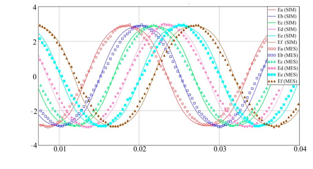
A prototype of the 7×4 slot and 6×4 pole three-phase quadruple winding machine was made (figure 8 a-b) and this was tested by connecting in parallel 2 of the 4 stator units and loading them respectively on a resistor star and on a diode rectifier bridge (figure 8 c-d). The results of the tests are shown in figure 9, where the waveforms recorded on the test bench are compared with those obtained by simulation of the machine with the finite element method in the time domain.
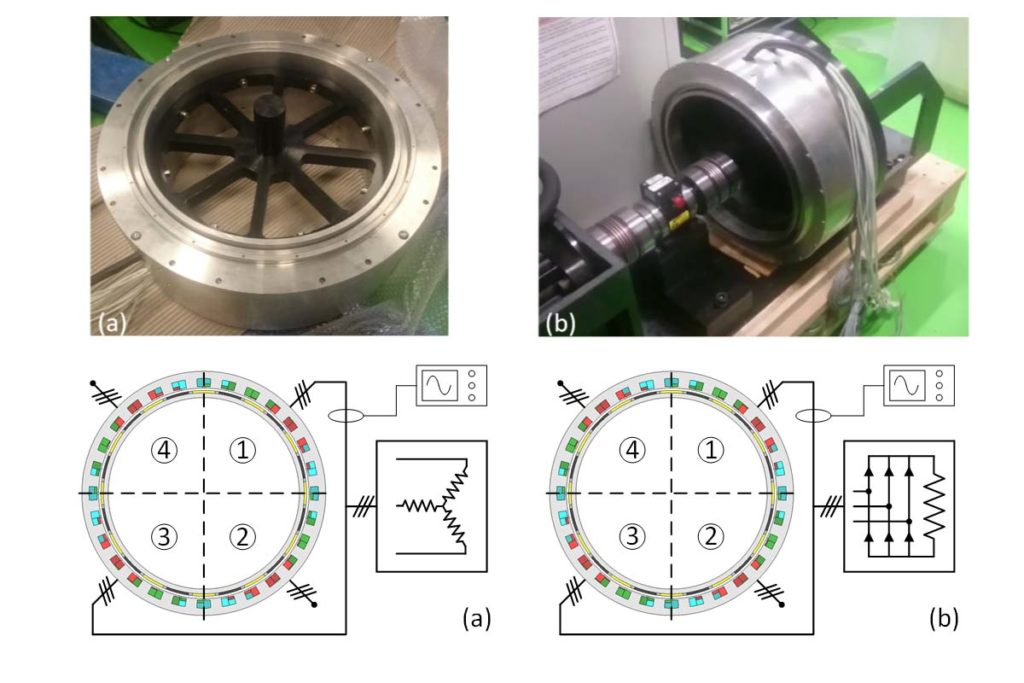
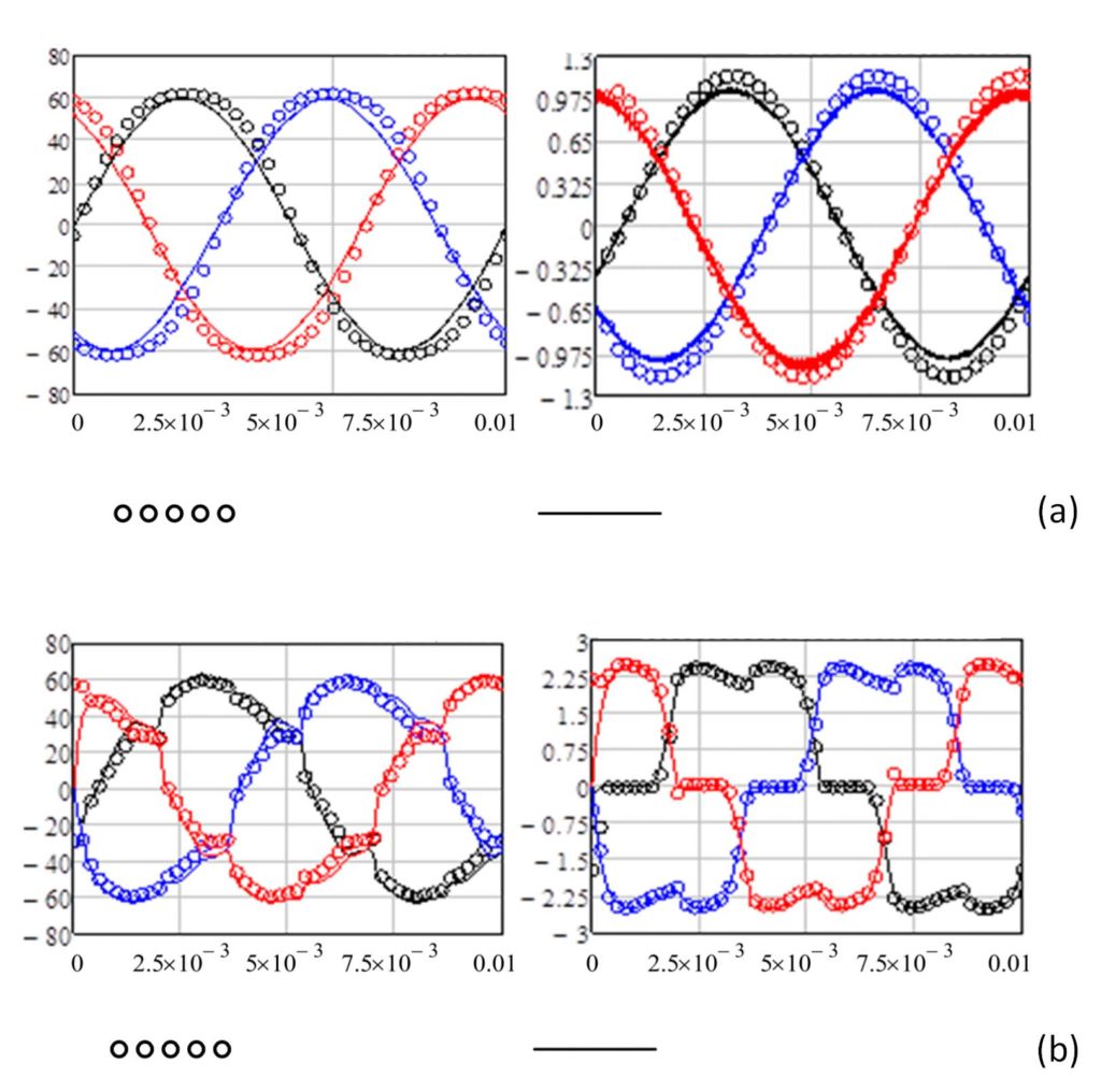
The results confirm the perfect symmetry of the machine and the excellent agreement between design forecasts and experimental behaviour. Similar waveforms, which do not show any unexpected phenomenon as a consequence of the choice of an unconventional winding, were also obtained by loading the other two machine units.
Professor Tessarolo concludes: “It can be said that the realization of concentrated electric windings, beyond traditional shapes and the classical limitations assumed for your project, have wide margins of optimization and extension. Provided that they are implemented on a multi-layer basis”.
It has been shown in these pages how, with appropriate numerical optimization techniques and the operating methodology proposed by Professor Tessarolo, it is possible to drastically reduce (even by more than 50%) the losses that originate in the permanent magnets due to eddy currents, with a small reduction in the torque which the machine is able to develop. It was also shown that, through similar optimization techniques, it is possible to design machines with concentrated windings with combinations of number of slots and poles traditionally considered incompatible or not feasible in symmetrical form. Finally, some application examples have been illustrated of how this can be of interest, especially (but not only) in the design of concentrated winding machines with more than three phases. It is therefore an operational approach and a methodology that, in fact, provides useful elements for greater freedom in design and execution.
Solar cars, a four-seats racing vehicle

The Sun Energy, integrated by an appropriate level of technology for electric motors, can represent a valid alternative to conventional mobility. The four-seats solar cruiser, called “Emilia 4”, conceived by Bologna University in the ambit of Onda Solare project, is the first and unique solar racing vehicle for more passengers ever implemented in Italy. At its first exit, it won the American Solar Challenge, one of the most prestigious competitions in the world for solar cars.
Fiorenzo Sorcinelli
It dates back to just few weeks ago Onu scientists’ umpteenth alarm aimed at sensitizing worldwide governments about the imminence of a climatic change owing to the massive emissions of greenhouse gases into the atmosphere. The transport of freights and people has its own share of these emissions. We should just consider that in Europe more than 1/3 of energy is used in transports and it is obtained from petroleum products (petrol, diesel, LPG…). For the only Italy, and just for the road transport, this implies over 30 million tons of oil that every year literally go up “in smoke”. Then, we must add to this smoke the CO2 contribution amounting to 900,000 (equivalent) tons of natural gas and 1.1 million tons (equivalent) of biofuels … Nowadays, the urgency of an intervention is so evident and undeniable that the primary automotive industries are competing through the continuous release of hybrid or fully electric models.
The sustainable mobility is a crucial matter and they are working hard at it but the contribution of electric cars, even if in fast expansion, still represents a negligible market share (0.01%). Moreover, the perception that the electric does not solve the general problem of the pollution, but simply moves it elsewhere, is diffused.
This explains why, in this panorama, solar cars, powered by solar energy converted into electric by photovoltaic panels, succeed in catching increasing attention. These cars, in fact, besides featuring zero emissions, are conceived to reduce the energy consumption drastically by means of ultra-light cars, a perfect aerodynamics and the highest efficiency. In general, they are advanced prototypes, almost always single-seater, designed and implemented by forefront Universities and Research Centres, to take part in solar competitions that, like in the case of Formula 1 in automotive field, represent a test bench to test new technologies, innovations and solutions.
Concerning this, it is worth highlighting that the design of a solar vehicle is influenced by the quantity of energy input into the car, quite limited under standard conditions. It is so understandable how, even if some of the prototypes manufactured in these years have been ideated for public uses, commercial models of solar vehicles are not available, yet. On the contrary, at least observing them, these vehicles seem quite distant from a daily use.
Recently, however, the organizers of these competitions have adopted a strategy of competition regulation modification that leads to approach these vehicles to conventional transport means as much as possible, creating interesting synergies with the industrial world.
This direction is followed by the recent introduction of multi-passenger cruisers, a category devised in opposition to single-seater models. These new vehicles must comply with more severe requisites due to the presence of passengers, for instance concerning the safety and driveability. However, even the electric powertrain must evolve beyond a wider “battery pack”: inner spaces must be exploited differently, mechanics must be repositioned, the braking recovery becomes even more essential, and so on.
Concerning cruisers, then the multi-passenger concept must be adopted already in the design philosophy: in fact, it is no longer sufficient that you are implementing a solar car with which to run in the desert, but instead a functional and sustainable means of transport.
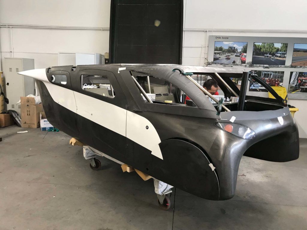
At Bologna University, in the ambit of Onda Solare project, with the implementation of the four-seats solar cruiser called “Emilia 4”, first and unique multi-passenger solar race vehicle ever made in Italy. With excellent results, considering that at its first exit it won the American Solar Challenge, one of the most prestigious competitions in the world for solar cars.
Design
The vehicle was born from a design and construction course based on the implementation of competing engineering instruments, rarely used in such integrated form, achieving a product unique of its kind. It features a high technological content, especially in terms of materials, structures, processes and related optimization logics that have implied the creation of overall Cad 3D models, the execution of manifold functional details for each component, the structural and fluid-dynamics controls with Fem codes, including simulated crash-tests, to proceed then to the prototyping of scale models, using more or less traditional techniques and materials, such as scale tests in wind tunnel, multi-objective optimization of geometries, also through the development of apposite codes.


The final data of the vehicle are the following: overall dimensions 4600x1800x1200mm; empty mass (batteries excluded) of 230kg; total weight of 620kg (4 passengers included); front surface of 1,60 m2; wheel base of 2.772 m; Cx of 0,20.
Electric characteristics
In terms of electric powertrain, the vehicle is designed for an average absorption of 21Wh/km at the cruise speed of 50km/h, consumption that allows an autonomy of about 750km.
The photovoltaic panel consists of 5m2 of monocrystalline silicon, with 326 high-efficiency SunPower cells (24% at 25°C) for a maximum panel power of 1,1kW. The converter for the photovoltaic panel is of Boost Converter typology, distributed generation, with a nominal power for each single stage of 200w and 98% overall efficiency.
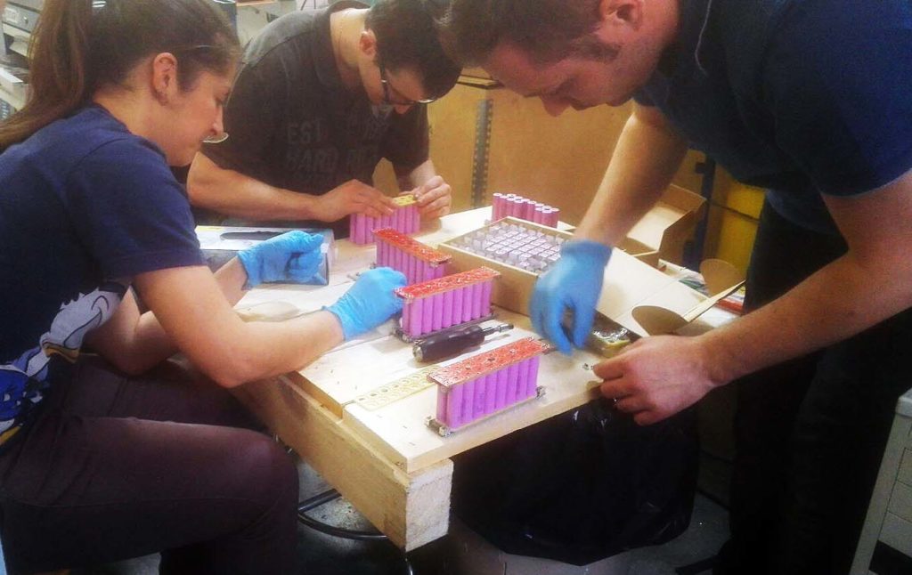
The battery pack, which weighs 85kg of which 64kg of battery, is positioned in the central tunnel and features these characteristics:
- 1344 Samsung lithium ion cells with nominal capacity of 3.4Ah
- 48V nominal voltage
- 331,2Ah current intensity
- 16,1kWh total energy.
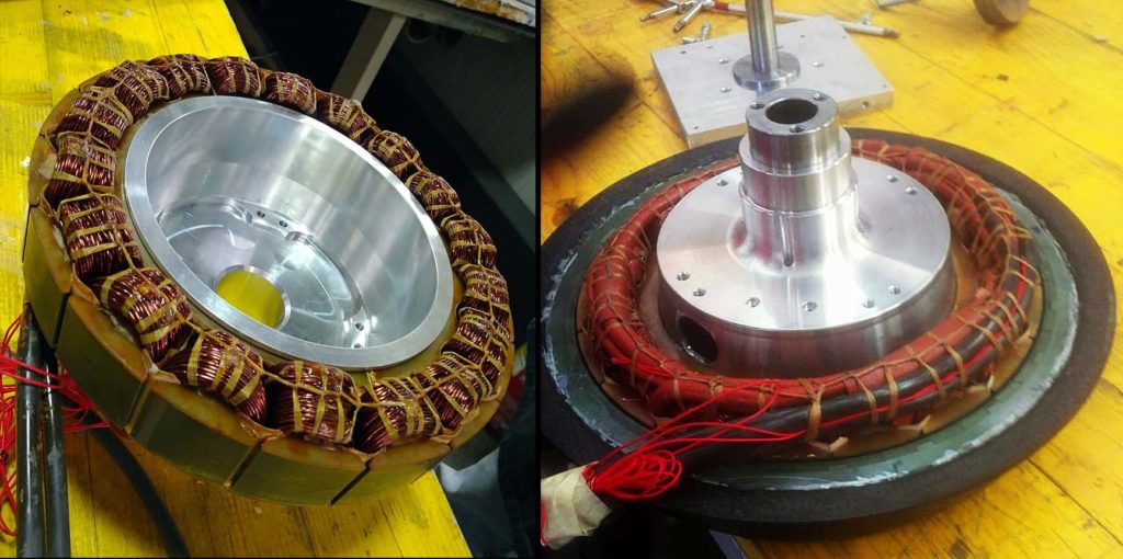
Motors consist of two surface permanent-magnet synchronous motors assembled on the rear wheels by means of external rotor directly coupled with the wheel and stator on the structure. Each motor, weighing 11kg, shows the following characteristics:
- 1300W nominal power;
- 3000W maximum power;
- 35Nm nominal torque;
- 125 Nm maximum torque and it allows a maximum speed of 110km/h.
The traction inverter is a three-phase inverter, with field orientation control able to deliver a maximum current (x1) of 200 ARMS.
This solution results in the 97% motion transformation efficiency.
The constant control of the entire electric powertrain is assured by 2700 sensors.
Structure
For the frame, they have chosen a carbon fibre monocoque body, vital for the implementation of a high-performance vehicle, light but also resistant and stiff. The structure has been made through processes in autoclave on carbon fibre tools, to grant dimensional stability during the polymerization cycle. These tools, on their turn, have been rolled on high-density aluminium or foam models, milled on big CNC machines. Most parts are composed by sandwich structures, to obtain the utmost resistance with an extremely low weight. We so obtain a vehicle that we judge the lightest in the world survey of “solar multi-occupant car”. The vehicle safety is based on the construction of a sturdy monocoque structure, made of reinforced composite, on which are mounted the other essential structural (and non-) elements. Only significant exception to the use of carbon fibre is in the safety cage, made with titanium alloy bars, mutually welded and bolted in the carbon fibre frame.
The whole solar powertrain, including electric motors and all energy management and control systems, has been developed by the Inter-departmental Centre on Advanced Engineering and Materials of Bologna University, under the coordination of prof. Claudio Rossi.
Conclusion
This solar car has been a real challenge to network the manifold available competences on the national territory. However, it has also represented the emblem of their success. Able, last July, to cross the United States, from Nebraska to Oregon, travelling for 2,700 km and overcoming a pass of the Rocky Mountains at the altitude of 2,500 m, it transported 4 people on board, without ever turning to the grid recharge: only solar energy, or directly in nice days, or the one stored in the battery during the many thunderstorms. All this was awarded by the victory in the competition and by the technical prizes by “Mechanical Design Award” and “Battery Pack Design Award”.
They now work at the homologation and at the registration (category Le7) while a long road starts, the one that might lead to a real industrialization of solar vehicles. We believe, however, it is already clear that the Solar Energy, integrated by an adequate level of technology for Electric Motors, can represent a valid alternative to traditional mobility … if we want to devise something that can really protect our Planet.
Noise reduction by means of isotropic super finishing

To reduce the noise of electric motor transmissions, the technique that seems to offer the best performances for industrial productions is a variant of the so‑called isotropic super finishing (ISF), which can combine the typical finishing of the conventional ISF with the creation of compression stress states that are typical of the shot peening.
Francesco Chichi, Paolo Marconi
As you can easily guess, the shift from the reciprocating motor to the electric motor has unavoidably exerted a big impact on the relative transmission systems, both due to the different modalities of power delivery and to the different rotation speed. Less intuitive is how the passage to the electric motor has also implied the appearance of new problems, or better, has made some characteristics, which previously did not involve any criticality, emerge as problematic. Noise is one of them: first, due to the diminished typical noise of the propulsor; secondly, due to the increase of rotation speeds, which has implied a correspondent translation towards high frequencies also of the noise produced by gears, even more entering that range of frequencies that human ears hear as most “annoying”.
Therefore, for transmission systems intended for electric motors, the reduction of gears’ noise becomes fundamental, noise decrease that unavoidably is achieved through an optimization of the surface finishing of the same.
Unfortunately, precisely the different characteristics of power delivery of electric motors lead to the adoption of gears with increasingly small sizes compared to traditional ones, fact that undoubtedly does not support surface finishing processes. In this complete survey, the technique that seems to offer the best performances for industrial productions is a specific variant of the so-called isotropic super finishing (ISF), variant that also succeeds in matching the typical finishing of the standard ISF with the creation of the typical compression stress states of the shot peening.
Isotropic Super Finishing
With the term of “Isotropic Super Finishing” (often indicated with its acronym ISF) it is meant a vibration finishing treatment where the abrasive action of media on the surfaces of the components to be treated is enhanced by the presence of specific chemical agents.
Such chemical agents can selectively etch the asperities of the material, asperities that, after having been etched by the chemical action, are gradually removed by the mechanical action of media.
The primary target of such treatment is carrying out surface finishes with roughness in the order of 0.02 micros through a process at environmental temperature, granting an absolute uniformity of component profiles, with side benefits given by the annulment of eventual states of residual surface stresses and a slight increment of surface hardness.
In this of its formulations, ISF has been present on the market for about thirty years now: in this article, we are instead presenting a further implementation in which the chemical agent in liquid form is replaced by dedicated abrasive pastes, in order to achieve a process that not only allows an even better surface finish but can also perform surface stress states of compressive type that are partially analogue to those attainable through shot peening.
In its standard setup, ISF can be considered a derivation of the conventional tumbling barrel, those vibrating containers where components that need a cleaning of burrs, edges, witness bars or other macro-asperities are plunged into a “bed” of media having opportune hardness, shapes and sizes, and let vibrating for a long time (typically in the order of hours), until when the mechanical contact between media and pieces achieves the removal of this macro-asperities.
In the ideal case, the contact between media and element should occur tangentially to the surface of the element itself as much as possible, to obtain a removal of asperities but without creating new indentations on the material because of perpendicular clashes to the surface itself.
The limit of the traditional tumbling resides precisely in this: the removal of asperities occurs anyway for the mechanical effect of the collision between media and asperities of the material, shock that, even if controlled, will always and anyway have perpendicular components to the surface, and not only tangential to it.
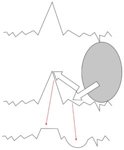
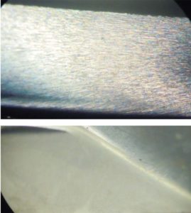
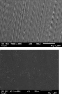
This means that prosecuting “endlessly” a tumbling treatment, we cannot expect a corresponding “endless” improvement of smoothing because media, after removing asperities up to a certain level, become a source of damaging for the surface, too (fig. 1).
In the case of ISF, conventional media are combined with a chemical agent able to etch the mechanical resistance of the base material: in this way, media must act on a material whose macroscopic characteristics of mechanical resistance are diminished, and therefore the material removal is notably facilitated.
This allows using so less “aggressive” media from the mechanical point of view that they can no longer constitute a source of damaging for the base material, thus making finishing a progressive “flattening” by parallel levels (fig. 2).
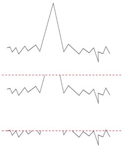
This means that the process can be carried on “endlessly” in time, progressively incrementing the surface removal of the material and then finishing, reaching surface finishes with roughness in the order of 0.02 μm, moreover with surface “textures” characterized by a development essentially in depression, extremely favourable for the lubricant tribology (fig. 3).
Contextually with these, so to speak, geometric effects, a further benefit induced by ISF is an annulment of eventual residual traction stresses on the surface.
Such phenomenon is widely documented in literature and, in general, we can assume that such effect is connected to the fact that the material removal anyway constitutes a relaxation element of stress states (several measuring techniques of residual stresses are just based on this presupposition), and that such removal is particularly accentuated precisely where residual stresses are more tractive (just think of the stress corrosion phenomenon).
Figure 5 reports a comparison of the stress states present on a sample of austenitic steel purposely hardened to induce traction surface stresses: the determination of residual stresses was carried out by means of X ray diffraction (XRD technique) by 2Effe Engineering laboratory at Soiano del Lago (BS), with the in-depth analysis carried out by progressively removing the surface material through electrochemical etching.
From liquid to paste
As highlighted by realities of industrial productions of fast transmission gears, it is by now almost impossible assuring their demanded performances, especially in terms of duration and fatigue strength, without turning to the shot peening treatment, a treatment that, in extreme synthesis, provides for hitting the surface of the component under machining with a flow of particles projected by a nozzle under the thrust of compressed air, so that the combination of:
- Kinetic energy owned by particles;
- Mass of particles;
- Material of particles (or, more precisely, their breaking point);
- Hardness of particles in relation with the hardness of the material to be treated
- succeed in inducing on the material surface a plastic deformation in orthogonal sense to the surface itself.
In its turn, due to the well-known Poisson effect, to such plastic deformation that is orthogonal to the surface, corresponds the onset of compression stress states in parallel to the surface itself, according to the mechanism illustrated overall in figure 5.
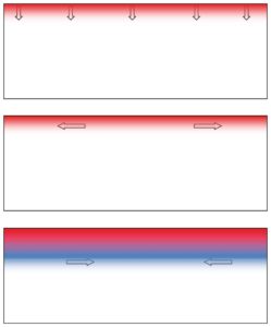
Therefore, it is a treatment of essentially mechanical nature, because the ameliorative effects it introduces are mechanical and the mechanisms through which such effects are generated are mechanical, too.
From the quantitative point of view, the induced stress states take a maximum absolute value up to 70% – 80% of the yield point of the material, and their effect propagates up to about 0.1 mm of depth.
Unfortunately, just their geometrical conformation, especially the adoption of a generally very small module, can highly complicate the efficacious application of the shot peening treatment to the gears of electric transmissions, precisely because of the geometrical difficult of “wetting” perpendicularly, with the media flow, the contact surfaces of the tooth.

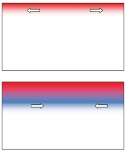
Luckily, the collision with the media perpendicularly projected to the surface is not the only modality to achieve a controlled plastic deformation of gear surfaces (or of any other component): it is well-known that also stock removal machining can achieve a similar effect, as the stock removal passes through a “tear” in which the material is first brought to plastic deformation and then to exceed its elongation point (fig. 6).
Concerning the surface left free from the cut, the plastic deformation by traction that has preceded the chip separation leaves, due to an elastic spring-back mechanism resembling the one just seen for the shot peening, an elastic compression state in parallel to the surface itself (fig. 7).
The inspiring principle of ISF with abrasive pastes precisely consists in using vibration-finishing media to carry not so much a chemical agent but instead an abrasive paste, taking back the surface stock removal process from a chemical ambit to a mechanical ambit and actually reproducing a grinding process on infinitesimal scale, as the grain of the abrasive paste is the tool and the media is the tool holder.
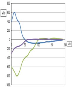
The experimentations personally carried out on steel samples, previously seen, have led to determine, for this treatment, surface stress states that are qualitatively analogue to those induced by the shot peening, even if with quantitative values reduced from 80% – 70% to 30% – 25% of the yield point and penetration depth decreased from 100 μm to about 30 μm (fig. 8).
Conclusions
The so-called “vibration finishing treatments”, in other words all those treatments that are based on the repeated relative contact between the component under treatment and specific media acting also as vector of a third substance, are included by full right in the field of surface engineering, inside what I define “modification treatments”, i.e. aimed at enhancing the characteristics of the material surface through endogenous modifications, and not through the coating and deposition of exogenous material.
Isotropic Super Finishing, ISF in the international technical language, is a specific vibration finishing treatment that sets the target of the progressive removal of surface material through the combination of a chemical action that diminishes the resistance of the protruding material and of a mechanical action of media removing the so weakened material, in a finishing process that can be theoretically prolonged endlessly but that actually, with execution times of 6-12 hours, grants a finishing in the order of 0.02 μm on any engineering material.
A new approach to ISF provides for the replacement of the chemical agent with an abrasive paste that, conveyed by media, obtains the removal of the protruding material with a purely mechanical process mirroring what happens in a grinding operation. In this case, the material removal mechanism by exceeding the breaking point in elongation, grants the creation, by reaction, of elastic compression states on the surface, with a mechanism partially recalling the shot peening; in comparison with the latter, stress states are inferior in both absolute terms and in terms of reached depth, but with the advantage of a much better surface finish.
Acoustic monitoring and background noise in industrial environment

Since any interruption in the manufacturing process can cause a serious financial loss for the company, it is very important to prevent unplanned shutdowns of electric machinery. Hence, monitoring and diagnosing the health of electric motors is crucial, and continues receiving more and more attention. One of the possibilities for performing diagnostics of electric machines is by analysing sound emitted by object of interests. The quality of acoustic monitoring is very much dependent on the background noise of the environment in which the machine is operated. Some attempts to create condition-monitoring methods based on acoustic analysis were made in the past (Refs. 1-4).
Recently, acoustic analysis has attracted more and more attention, and has been applied in many fields – speech recognition, for example. However, condition-monitoring methods based on acoustic analysis are still considered difficult to implement in an industrial environment due to the background noise.
The easy availability today of data collectors and sensors as accelerometers or current probes drives the use of many condition-monitoring systems based on those measurements. However, it is still very often the case that site engineers are asking for inspection of the machine when they notice abnormal sound.
Instead of isolation of the sound and its analysis, a typical “solution” is to perform measurements of vibration, current, temperature or voltages that are not always indicative of the problem. Even though what was reported was abnormal sound, existing solutions are trying to detect the fault by various types of measurements, as opposed to showing that sound is emitted by a specific part in the first place. This, in turn, might limit the amount of possible diagnostic decisions, thus limiting the amount of required effort.
For this reason, in many cases the first diagnostic attempt is made by highly experienced engineers who are able to initially detect and diagnose the problem by simply listening for the sound source. For many years, diagnostics in the industry were performed “by ear,” with subsequent assessment of the emitted sound. Still, the influence of background noise can strongly affect the quality of such a judgment.
Today’s trends in the job market lead to a situation where there is less and less people who are experienced enough to judge the condition of an object by listening to the sound it makes. It is the result of the fact that many people prefer to do office work rather than working in an industrial environment. As is shown, in the Global Employment Trend document (Ref. 5), or in the list of the top 10 jobs forecast for next decade (Ref. 6), this situation will be even more prevalent in the future. However, there remains a necessity of doing the initial investigation of objects to localize the abnormal sound to perform immediate action.
A solution of the described problems might lie in the usage of acoustic analysis for objects-of-interest diagnostics. Thus far, it has been relatively difficult to create a reliable, acoustic-based condition monitoring system due to the fact that sound measurements are always affected by background noise. However, recent technologies like acoustic cameras are able to successfully localize specific sound components and thus remove the influence of such noise (Refs. 7–8).
A variety of faults that can occur in induction machines have been extensively studied and many monitoring methods have been proposed to detect problems (Ref. 9). Most of those methods for condition monitoring of electric motors utilized vibration or motor current signature analysis (MCSA) (Refs.9–11). While vibration and current signature analysis-based monitoring techniques are well known and well-accepted, acoustic measurements are not so popular in industrial application.
This paper describes a diagnostic method for induction motors based on acoustic measurements, while vibration analysis is used as a reference for assessment of the value of acoustic measurements.
Measurements Tools
Acoustic camera
The idea of the acoustic camera is to do sound source identification and quantification, and to create a picture of the acoustic environment through the processing of the multidimensional acoustic signals received via microphone array and to overlay that acoustic picture on the video picture (Ref. 7). Other possible acoustic camera applications include use as test equipment for non-destructive measurements for sound identification in vehicle interiors and exteriors (Refs. 7–8 and 12); trains and airplanes (Refs. 13–14); and for measurement in wind tunnels, etc. Additionally, some studies show the application of acoustic camera for unmanned underwater vehicles (Ref. 15), robots and robotized platforms, etc. It can also be used for passive acoustical sensing in battlefield environments (Ref.16). In this work, a 48-microphone acoustic camera was used for sound measurements; parameters for the microphones are presented in table 1.
 Acoustic holography technique was used for analysis of the sound source. Acoustic holography technique is a method that is used to estimate the sound field near a source by measuring acoustic parameters away from the source via microphone array. This is a well-known technique and its description can be found in (Refs. 16–17).
Vibration measurements
Vibration measurements are one of the most popular methods for condition monitoring of electric motors. Typically, piezoelectric accelerometers are used for measurements of the vibration. For the purpose of the present work, vibration measurements were taken as a reference for the sound measurements. Vibrations were collected with ABB’s MACHsense-P condition monitoring tool. MACHsense-P is a walk- around condition monitoring service tool provided by ABB that specifically focuses on electric motors. Vibration signals were measured using 4 simultaneous data capture channels and analysed for mechanical and electromagnetic defects. The frequency range used for analysis by MACHsense-P tool is from 0 Hz to 12,800 Hz. The vibration analysis presented in this paper is embedded functionality in the MACHsense-P tool.
Measurements analysis and comparison
All vibration and acoustic measurements where done in an industrial environment. Since induction motors are the most widely used machines in industry (Ref. 18), two of the same type three-phase induction motors were chosen. Nameplate details of the motors are presented in Table 2.
 Both motors were located relatively close to each other, and both of them were driving centrifugal pumps of the same type through direct coupling. Both motors where operating at the same load level. Motor case 1 is considered healthy while motor case 2 is considered to have a combination of static eccentricity and soft foot. As soft foot typically results in static eccentricity, this combination of faults is very common.
Results based on vibration measurements
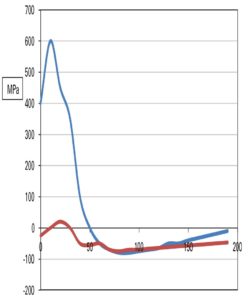
For both of the motor cases, vibration sensors were located horizon- tally on the center of the body of the motors. Figure 1A presents a vibration spectrum of the healthy motor case while Figure 1B presents a vibration spectrum of a combination of static eccentricity and soft foot motor case. Since static eccentricity can be typically visible in low-frequency range, both figures present frequencies from 0 Hz to 200 Hz. You may notice that Figure 1B contains a high peak – at around 100 Hz.

The value of this peak is above 0.12 gs, while in Figure 1A this peak is smaller than 0.02 gs. As presented in (Ref. 12), static eccentricity causes additional forces visible in vibration at frequency fecc – given by following equation:
fecc = 2 ∙ fline
Where fline is power supply frequency. In the above case, both motors were supplied by 50 Hz; therefore static eccentric-related frequency fecc is visible at 100 Hz. By taking the amplitude of fecc frequency as the static eccentricity indicator, it is clearly visible that the motor in case 2 reached a higher level of static eccentricity than the healthy motor from case 1. With the MACHsense-P the indicator of static eccentricity is calculated automatically.

Results based on acoustic measurements
For industrial applications, when performing measurements using a microphone, background noise can- not be avoided. The background noise can be filtered out by post-processing methods of the measured signals. This is possible due to the different nature of the measured sound. The background noise (including the aerodynamic noise of the cooling device) is usually a broadband signal with a more or less constant spectrum (Ref. 1). On the contrary, the induction machine generates sound that is characterized by many pure tones – at least for the sound produced by electromagnetic origin. Reference 1presents a method where before operating the induction machine, a measurement of only the background noise is conducted. This spectrum of the measurements is later subtracted from the measured spectrum, with the induction machine in operation. However, this noise filtering approach is not accepted in industry because it affects the industrial process.
Reference 11 describes a method that isolates the frequencies related to the motor presented in electric current measurements. The same approach can be applied for vibration or acoustic signal. As presented in (Ref. 11), by knowing motor parameters and motor slip, all the frequencies related to motor condition can be identified. Likewise, all motor-related frequencies can be found and identified in the acoustic signal, even if the signal contains back- ground noise.
Figure 2 presents an acoustic spectrum of average signal via microphone array.

Figure 2A presents acoustic spectrum of a healthy motor case, while Figure 2B presents an acoustic spectrum of a combination of static eccentricity and soft foot motor case. Both figures are obtained for frequencies ranging from 0 Hz to 200 Hz. Similar to vibration cases, it is possible to notice that Figure 2B consists of a high peak at around 100 Hz, while Figure 2A does not. Value of this peak is above 600 mPa, while in Figure 2A this peak is smaller than 350 mPa. Those results are very similar to vibration-based results, and they are clearly indicating static eccentricity; however, in case of acoustic signal there is no assurance that this frequency emanates from the motor.
To solve this problem, the acoustic holography technique can be applied to find the sound source of the frequency of interest, in this case, 100 Hz.

Conclusions
In this paper, an acoustic-based technique for the condition monitoring of electric motors was presented. Vibration analysis was used as a reference for assessment of the value of acoustic measurements. Acoustic measurements were performed via 48-microphone acoustic camera. Two induction motor cases were examined a healthy motor case and a combination of static eccentricity with soft foot case. For fault case, respective frequencies were identified in both vibration and acoustic signal. Based on acoustic holography technique, the fault-related acoustic frequency source was localized in the center of the body of the faulty machine. As presented in the results section, one can say that acoustic signals can be successfully used for condition monitoring of electric motors in noisy industrial applications. Obviously, single acoustic signal is disturbed and noisy compared to vibration signals; therefore sound localization technique via acoustic camera was needed to solve this problem. An additional benefit of sound analysis is the fact that the acoustic sensors need not be attached directly to the motors, which is often difficult in industrial applications.
(Maciej Orman and Cajetan T. Pinto)
References
[1] Van Riesen D., Schlensok C., Henrotte F., Hameyer K.: “Acoustic measurement for detecting manufacturing faults in electrical machines”, 17th International Conference on Electrical Machines ICEM, (2006)
[2] Verma S. P.: “Noise and vibrations of electrical machines and drives; their production and means of reduction”, International Conference on Power Electronics, Drives and Energy Systems for Industrial Growth, Vol. 2, pp.1031, 1996
[3] Verma S. P., W. Li: “Measurement of vibrations and radiated acoustic noise of electrical machines“, Sixth International Conference on Electrical Machines and Systems ICEMS, Vol. 2 (2003), pp. 861
[4] Gaylard, A., Meyer, A., Landy, C., A. “Acoustic evaluation of faults in electrical machines “, Seventh International Conference on (Conf. Publ. No. 412), Durham, p. 147 -150
[5] Employment Trends unit of the ILO Employment Sector, “Global Employment Trends 2012: Preventing a deeper jobs crisis”, International Labor Office, Geneva, 2012.
[6] WorldWideLearn “Top ten jobs”, WorldWideLearn.com Copyright, Quinstreet Inc., 2012.
[7] Miljko M.Eric., 2011, Some Research Challenges of Acoustic Camera, 19th Telecommunications forum Telfor,Page(s):1036-1039
[8] Ulf Michel, “History of acoustic beamforming”, Berlin Beamforming Conference (BeBeC) 2006, 21-22. Nov.2006
[9] Tavner P.J., 2008, Review of condition monitoring of rotating electrical machines, IET Electrical Power Applications, Vol 2(4), Page(s): 215-247
[10]Orman M., Orkisz M., Pinto C. T., 2011, Slip Estimation of a Large Induction Machine Based on MCSA, Diagnostics for Electric Machines, Power Electronics & Drives (SDEMPED), IEEE International Symposium on, Bologna, pp. 568 – 572, 2011
[11]Orman M., Orkisz M., Pinto C. T., 2011, Parameter identification and slip estimation of induction machine, Elsevier, Mechanical Systems and Signal Processing, Vol 25, Page(s): 1408-1416
[12]S.Guidati, “Advanced beamforming techniques in vehicle acoustic”,Berlin Beamforming Conference (BeBeC) 2010.
[13]C.Cariou, O.Delvedier “Localizing aircraft noise sources with large scale acoutic antenna” 27th International congress of the aeronautical sciences
[14]J.S.Pascal, J.F.Li “Use of double layer beamforming antenna to identify and locate noise in cabins, EURONOISE, Finland, 2006
[15]Hans-Elias de Bree, Jelmer Wind, Erik Druyvesteyn, “Battlefield Acoustic”, Microflown ebook, chapter 21
[16]Korpel Adrianus, “Acoustic imaging and holography”, IEEE Spectrum, Volume: 5 Issue: 10, pp. 45 – 52, 1968.
[17]Mueller, R.K. “Acoustic holography”, Proceedings of the IEEE, Volume: 59 Issue: 9, 1971
[18]Long Wu, “Separating Load Torque Oscillation and Rotor Faults in Stator Current Based-Induction Motor Condition Monitoring”, Georgia Institute of Technology, 2007.
[19]M.Mijic, D.Masovic, D.sumarac Pavlovic and M. Adnadevic, “A Model of Planar Microphone Array Realized with Low-cost Multimedia Microphones”, Telecommunications Forum (TELFOR), pp. 1040 – 1043, 2011.
University of Perugia: the study on the efficiency of electric cars is starting

One of the hottest issues concerning the electric mobility is the motor efficiency. Concerning this, a study involves the University of Perugia, in the context of a graduation course in industrial engineering. The research programme involves also professors of triennial and master graduation courses in Industrial Engineering in Terni, as well as Genesi Energia company, operating in the sector of the electric mobility engineering and of manufacturing, stocking and use of electric energy from renewable sources.
The study provides for activities of modelling and experimental analysis in electric mobility applications and the creation of predictive models for the assessment of the charge efficiency and of autonomy depending on the mileage. Such predictive models, combined with experimental checks, will be applied on Renault Zoe electric car, made available by Genesi Energia.
«The analysis of efficiency and energy dispersion of the new electric mobility – explained prof. Ermanno Cardelli, director of the Engineering department of University of Perugia – is a still unexplored field that will be fundamental to work at the implementation of the distribution networks of electric energy on roads. Moreover, the research provides for the design and the implementation of a prototype of electric quadricycle with pedal assistance with photovoltaic panels on board: the design of the super light frame, combined with renewable energy sources on board, will allow achieving theoretically unlimited autonomy in day travels».
Electric flying motorbikes. Science Fiction?

In the collective imagination, it is associated with futuristic unreal movies. It seems instead that the electric motorbike is not so distant thanks to Horizon Aeronautics that will release an electric hybrid eVTOL hoverbike with an innovative system of variable-pitch hemispherical rotor.
The Hoverbike by Horizon, with a design studied to grant significant efficiency rises, features the look of a jet ski and it is powered by a compact hybrid-electric system.
The technological collaboration was signed with the innovative Blainjett Aviation start-up, which works at the aerodynamic propulsion. The developed solution is called Dynamic Variable Pitch (DVP), patented technology of the hemispherical rotors that allows generating higher speeds with smaller sizes.
What is the gap that makes the difference? To generate the forward thrust, instead of adjusting the angle of attack of a helicopter or of an eVTOL rotor, the DVP adjusts the pitch of rotor blades on half of rotors’ arc.
Concerning its overall dimensions, the aircraft will weigh about 380 kg and the sizes will be 2.70 metres per 1.20 metres, able to host from one to three passengers on board.
A super electric motor incoming

Winding-free, featuring excellent performances, low weight and volume. Here are the main features of the new motor at which is working the Emilia company Poggipolini, top player in titanium fasteners for Formula Uno and aerospace. The new motor will address aerospace and defence, but also the world of the electric traction for Motor Sport and high-end cars.
Concerning this, a key role will be played by the factory of the future “Speed Up Lab”, headquartered in the new factory at San Lazzaro di Savena, in an area of over 20,000 sq. m., close to the Manufacturing Center of Excellence inaugurated in 2019. Its mission is working in open innovation.
Recently, the company has established a partnership with Puglia startup Roboze to design and to manufacture the mechanical parts of electric motors, 3D printed with innovative materials such as Carbon Peek, a carbon-reinforced polymer. The collaboration will aim at accelerating the adoption of this new process technology, shifting from engineering to industrialization.
The technology of the new electric motors will be fully innovative and will precisely concern its operation, as well as materials, which will assure lower weight and simplification of architectures and manufacturing processes.