Volvo Electric Site to provide model for sustainable construction in China
To design and to manufacture in-house electric motors for the next car generation, Volvo Carshas inaugurated in Shanghai, in China, a new laboratory precisely dedicated to electric propulsion systems. This structure, in operation since last month, joins the unit that constantly develops electric motors in Gothenburg, Sweden, and modern laboratories for batteries in China and Sweden.
«Through in-house design and development processes, we will be able to perfect our electric motors, reaching higher and higher qualitative levels. Constantly ameliorating the overall performance levels of propulsion systems in terms of energy efficiency and comfort, we create an electric drive experience that exclusively identifies Volvo brand» – stated Henrik Green, Chief Technology Officer of Volvo Cars.
The laboratory activity will focus on the development of electric motors for applications in purely electric and hybrid cars based on the modular architecture for SPA 2 vehicles. The future of the brand is well outlined: the target is rising to 50% the share of fully electric models out of the total of global sales by 2025, with the remaining part constituted by hybrid models.
It is called REX4 Electra the hybrid tractor by Landini brand, trademark of Argo Tractors Spacompany, multinational of Argo industrial Group headquartered at Fabbrico, in Reggio Emilia province.
The vehicle, intended for crossing fruit and vegetable fields in a sustainable way, has won the Technical Novelty Eima International, too.
Propulsion is dominated by the 110 HP diesel engine that, through the generator and the battery, powers the two front electric motors, which deliver 12-kW power that can rise to 16-kW for each wheel.
In REX4, the novelty is positioned in the “bow” of the tractor, with fully electric front-wheel drive on suspended axle and sensors, electronic controls, generator and battery dedicated to the Brake Energy Recovery, the energy recovery in braking and deceleration phases.
The system, which is called Electra Evolving Hybrid, is managed by PMS, Power Management System, which supervises the operation of all devices, battery included.
What are benefits in terms of performances? We will achieve the 10% fuel saving, the 15% steering angle improvement, the 15% vibration reduction and higher transport stability.
A new manufacturing process yields highest conductivity copper composites at bulk scale. This is a discovery of researchers at Pacific Northwest National Laboratory (PNNL): they have increased the conductivity of copper wire by about five percent. Higher conductivity means that less copper is needed for the same efficiency, which can reduce the weight and volume of various components that are expected to power our future electric vehicles.
The laboratory teamed with General Motors to test out the souped-up copper wire for use in vehicle motor components. As part of a cost-shared research project, the team validated the increased conductivity and found that it also has higher ductility-the ability to stretch farther before it breaks. In other physical properties, it behaved just like regular copper so it can be welded and subjected to other mechanical stresses with no degradation of performance. This means that no specialized manufacturing methods are necessary to assemble motors-only the new advanced PNNL copper composite.
The technology can apply to any industry that uses copper to move electrical energy, including power transmission, electronics, wireless chargers, electric motors, generators, under-sea cables, and batteries.
General Motors Research and Development engineers verified the higher conductivitycopper wire can be welded, brazed, and formed in exactly the same way as conventional copper wire. This indicates seamless integration with existing motor manufacturing processes.
«To further lightweight motors, advances in materials is the new paradigm – said Darrell Herling of PNNL’s Energy Processes and Materials Division. Higher conductivity copper could be a disruptive approach to lightweighting and/or increasing efficiency for any electric motor or wireless vehicle charging sytem».
REE’s innovative architecture is becoming the cornerstone of the broadest range of electric and autonomous vehicles. Three platforms point to future EVs, including last and mid-mile delivery, commercial & MaaS vehicles. The platforms are based on the advanced REEcorner module which utilizes full X-by-Wire technology for steering, braking and drive all in the arch of the wheel, enabling a fully-flat chassis
The wide array of REE’s modular platforms offer unprecedented design freedom to create any EV; from last and mid-mile delivery vans to commercial vehicles and autonomous shuttles
«EVs, particularly e-delivery vehicles, are in huge demand, with growth drivers including global carbon-emission regulatory policies coupled with a boom e-commerce. There is also a rapid rise in ‘mobility as a service’ (MaaS). Our modular platform is set to revolutionize electric mobility and as we shared today, the journey is well underway. Our platform provides the perfect blank canvas for our customers on which to build EVs tailored to their needs, whether it’s a fully autonomous last-mile delivery vehicle, a spacious yet compact urban shuttle or a flexible delivery truck with higher load capability on a smaller footprint» – said Daniel Barel, REE Co-Founder and CEO.
REE’s modular platform technology enables customers to choose the size that perfectly suits their vehicle requirements while the company’s industry-unique technology offers a choice of REEcorner modules, each with different sizing based on platform weight, dimensions and targeted applications.
To face the growing market of the sustainable mobility in the United States, the Japanese company Hitachi has decided entering the segment of electric motors for battery vehicles.
The location where electric motors will be produced is in Kentucky, exploiting already existing offices and factories in Berea city, covering almost 260,000 square metres.
The news of the manufacturing stop for Yara Birkeland, the first autonomous-guide electric container ship, arouses the debate about the green future of intermodal logistics. The matter was the transition of the transport from road to sea, reducing noise, pollution and fine dusts, with more safety of local viability.
The means, focus of the project started by Vard and Yara International in collaboration with Kongsberg Gruppen, which designs and develops autonomous-guide systems for military and civil vehicles, has captured the attention of the entire world. The “green” container ship is aimed at delivering goods in Norway through fiords, transporting products from Porsgrunn manufacturing site to Brevik and Larvik cities.
The reduction of nitrogen dioxide and carbon dioxide emissions that would occur in the region are equal to those generated by about 40,000 travels per year of trucks.
The loading capacity of Yara Birkeland, which will cover a course of approximately 40 miles at a maximum speed of 10 knots, is equal to 150 TEU. Besides, also the loading and unloading phase will be sustainable: it will occur with electric equipment.
In the opinion of Svein Tore Holsether, president and managing director of Yara, “this new autonomous battery container ship accomplishes the transition of the transport from road to sea, reducing noise and fine dusts and improving the safety of local viability.”
The means was expected to be ready in the first months of 2020, becoming at fully autonomous guide in 2022, but Pandemic has postponed everything. Let us see …
For this piece of news, we move to the United States, in Massachusetts, where Draper company is accomplishing a great change in the world of electric motors through the introduction of electrostatic motors.
They are a new family of electric motors and generators not based on electromagnetic principles but on electrostatic principles; a patent that would make electric motors lighter and more efficient.
How have they achieved this technological turning point? The innovation is based on a radical technological disruption: motors that exploit the forces of electric fields, and not magnetism, to generate torque.
In the past, however, electrostatic motors were too weak and problematic to compete with their electromagnetic counterparts, for instance owing to the heavy weight, the low maximum rotation speed and the big volumes of dielectric fluid.
Nowadays, on the contrary, due to the progress of materials and design, Draper is actually developing powerful electrostatic motors that can make the difference. Draper electrostatic motor includes a cylindric rotor and a stator, with the electrodes positioned on a cylindrical surface inside the stator. Electrically conductive electrodes are mounted on the cylindric rotor and a dielectric fluid fills the space between rotor and stator to prevent the electret discharge.
This approach might bring various benefits to different applications of electric motors: for drones, for industrial robots and the electric mobility.
The Research Group at Department of Industrial & Information Engineering & Economics of the University of L’Aquila has been working for many years in the field of designing, prototyping and testing of innovative motors for automotive applications. It is recently involved in a H2020-GV European project focused on contributing to avoid the use of rare-earth magnets through the development of a next generation of electric drivetrains, ensuring the industrial feasibility for mass production while focusing on the low cost of the manufacturing technologies.
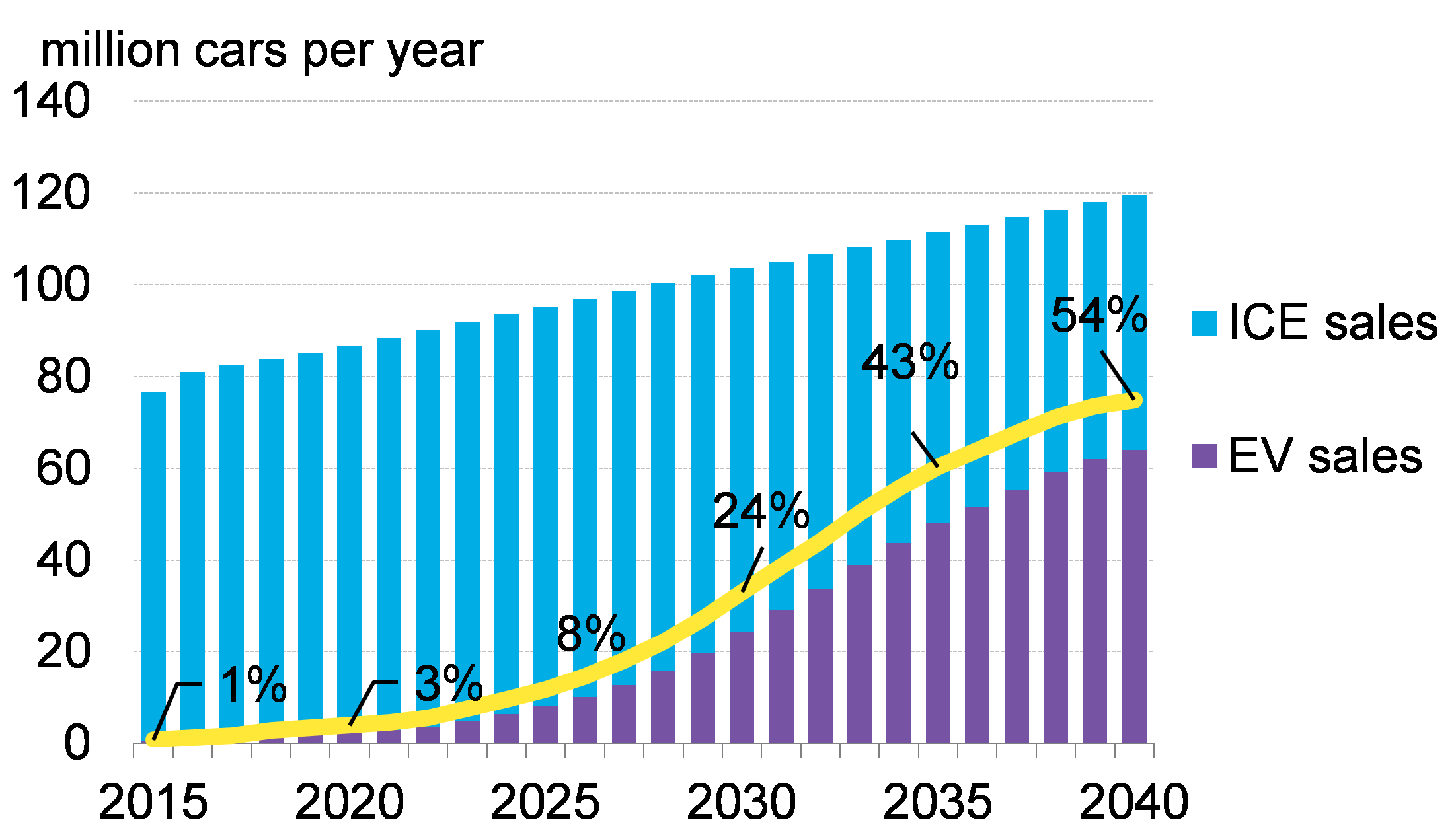
The impact of internal combustion engine on the environment has led to efforts to replace it by alternative propulsion systems, among which the electric motor has become the primary candidate. The electric car market is booming and in the next twenty years a surge electric vehicles (EV) sales is expected which should exceed that of traditional ICE cars, as shown in Fig.1.
The new technologies for energy storage and powertrains play a critical role in the development of the electric vehicle market. At motor level, key components and innovative materials must be integrated in the current motor designs. Recent advances in materials, power electronics, control systems have contribuited to new energy efficient and performant powertrains adopting innovative motor technologies.
1. Trend of electric car sales (Bloomberg New Energy Finance)
The basic characteristics of an electric motor
The requirements of the electric motors for EVs are different from the conventional ones used in the industrial applications. The most challenging specifications are a reduced size and high efficiency in an extended speed range. For good overloading and wide speed range capability, the machine is usually water cooled with a water jacket around the stator core.
The basic characteristics of an electric motor are the following:
1. high specific power and specific torque;
2. very wide speed range;
3. high efficiency over wide torque and speed ranges;
4. wide constant-power operating capability;
5. high reliability and robustness for vehicular environment;
6. reasonable cost.
Since the EV operates over a wide torque-speed range in various driving conditions, the motor design should be aimed to achieve overall energy saving over a driving-cycle of the vehicle (e.g. WLTP, NEDC, UDDS). There are many demands for developing propulsion systems with high power density, high efficiency and low cost.
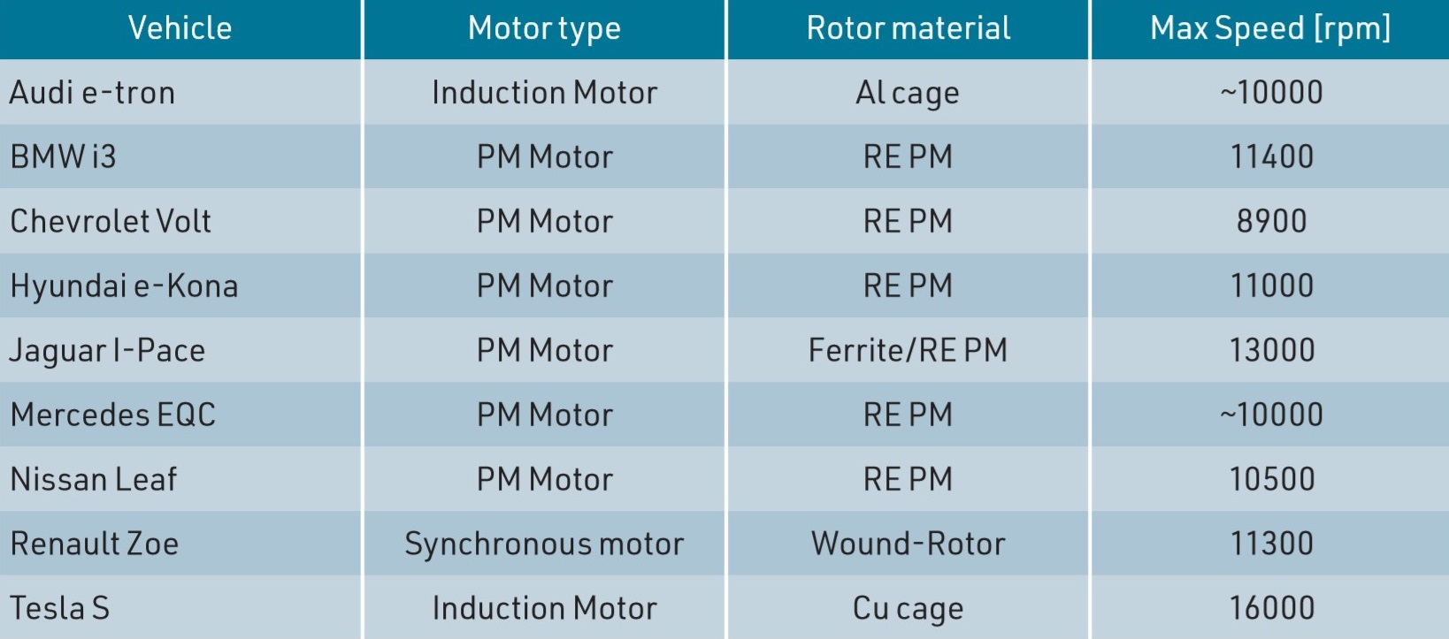
The research in this field has been intense in the past few years and different types of electric machines have been studied and proposed. The vast majority of motor solutions rely on Permanent Magnet technology using rare-earth magnets. Table 1 summarizes the existing electric vehicles in the European & US markets, specifying the technological solution for the traction motors.
Table 1: Traction Motors for Electric Vehicles
From the Permanent Magnet Synchronous Motor
The Permanent Magnet (PM) Synchronous motors are more attractive and the main advantages are their inherently high efficiency, high power density, and high reliability.
The PM motors are relatively easy to control and exhibit excellent performance, in terms of maximum torque per ampere control and optimal extended speed operation. Different types of PM machines are proposed according to the position of PMs in the rotor and can be classified as surface or interior mounted magnets.
The high and volatile cost of raw materials for magnets makes uncertain their long-term availability, especially since the electric vehicle technology is going to be manufactured in mass production. Also, PM motors present several technical drawbacks that limit the performances of the motor, in particular the demagnetization effect if the temperature of the motor exceeds its operating conditions. Therefore, there is a growing attention in alternative solutions that include rare-earth (RE) free machines or reduced RE-PM machines.
The Synchronous Reluctance Motor
The Synchronous Reluctance Motor (SynRM) is becoming of great interest in the recent years and represents a valid alternative for electric and hybrid vehicles due to its simple and rugged construction. The main advantage of the SynRM relies on the absence of the rotor cage losses or PM losses, allowing a continuous torque higher than the torque of an Induction Motor (IM) of the same size. Other important features are:
1. the rotor is potentially less expensive than PM motors and IM ones;
2. the specific torque is acceptable and it is not affected by the rotor temperature;
3. the field-oriented control algorithm is simpler with respect to the one of IM drives.
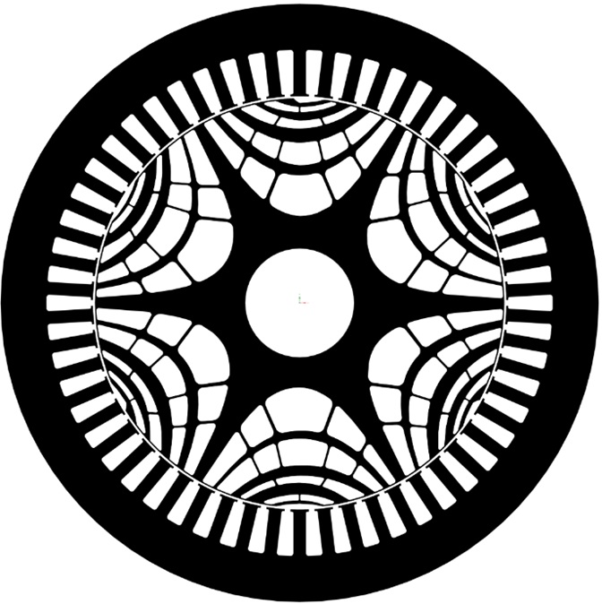
2. Cross section of the 200 kW SynRM
The conventional SynRMs are known for their lower specific (peak) power and specific (peak) torque (compared to the PM motors), higher noise and lower power factor.
Despite these drawbacks, it is possible to obtain high torque density and high efficiency motors through an optimized rotor design.
Specific power in SynRM is enhanced by increasing the rotor operating speed and the flux-weakening region. Nevertheless, the optimal geometry for motor performances needs to be refined to guarantee the mechanical integrity of the rotor at high speed.
New solutions for the power traction systems of electrical vehicles
The Research Group at Department of Industrial & Information Engineering & Economics of the University of L’Aquila has been working for many years in the field of designing, prototyping and testing of innovative motors for automotive applications. The Group is recently involved in a H2020-GV European project labelled “RefreeDrive” – Rare Earth Free e-Drives for low cost manufacturing.
Table 2: SynRM requirements for the target application
This project is focused on contributing to avoid the use of rare-earth magnets through the development of a next generation of electric drivetrains, ensuring the industrial feasibility for mass production while focusing on the low cost of the manufacturing technologies.
The aim is to study and develop new solutions for the power traction systems of electrical vehicles, based on Brushless AC electrical machines rare-earth magnet free.
Through the development in the electric motor topologies within the project, advanced performance has been achieved in terms of specific power, power density and efficiency, compared to a current electric vehicle taken as a reference (Tesla Model S 60). The ReFreeDrive Consortium is composed of 13 partners in six European countries and the team of University of L’Aquila took in charge the design of high speed Synchronous Reluctance motor (200 kW peak power) for a full-electric premium vehicle. The goal was to design a liquid cooled SynRM than could satisfy the imposed requirements shown in the Table 2.
Performances while respecting the target components cost
The avenues indicated above have required a complex optimization process for matching the desired motor performances while respecting the target components cost. Specific sizing procedures and optimization algorithms have been used for the design refinement and the proposed solution presents an innovative rotor structure with “fluid shaped” barriers and radial ribs.
Fig.2 shows the cross section of the 6-pole SynRM.The rotor with asymmetric shape has multiple “ribs” that connect the segments to each other axially and transversally: these connections maintain enough mechanical integrity in the rotor structure when rotational forces are applied at high speed.
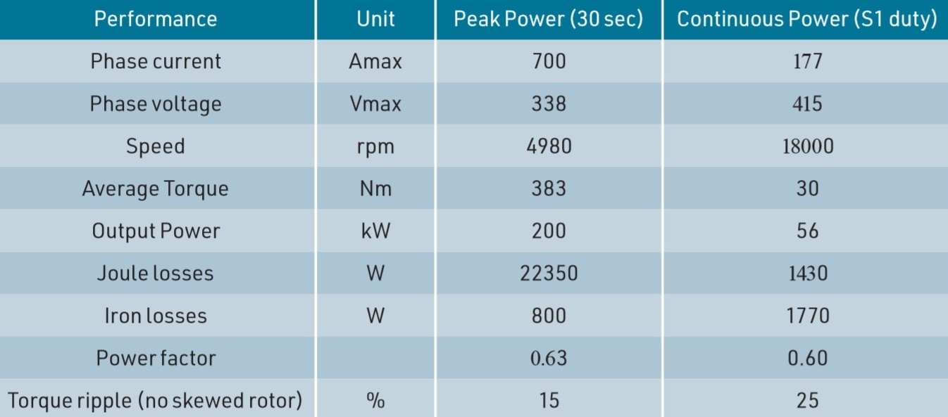
Table 3: Performance of the SynRM
The optimal positioning and the optimal thickness of the rotor ribs have been refined by the “topology optimizer” coupled to a mechanical Finite Element software; this algorithm has allowed to optimize the quantity and the positioning of the mass needed by a mechanical part to sustain the stress.
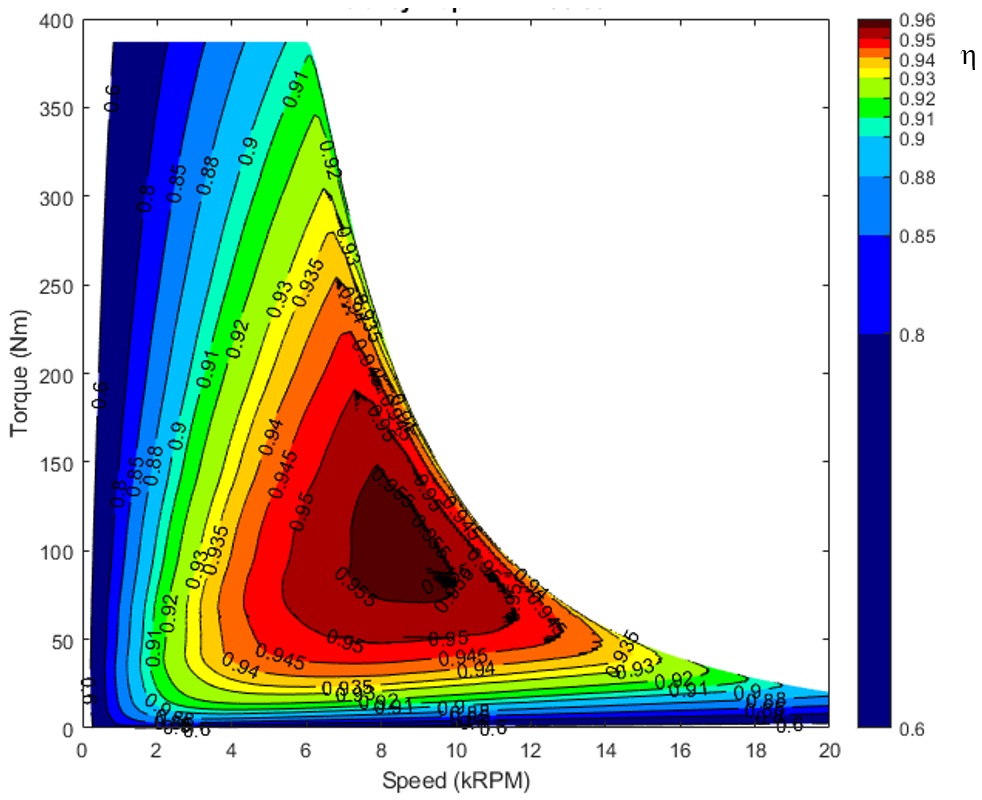
The main motor performance at peak power and continuous power are listed in Table 3 while Fig.3 presents the efficiency map in motoring mode: the peak efficiency is about 96% and the maximum torque is 383 Nm with a peak power of about 250 kW at 6200 rpm. At maximum speed (18000 rpm), the maximum power is 56 kW: these performances fully satisfy the requirements given in the Table 2.
3. Efficiency map of the SynRM
4. Rotor of the SynRM (1 pole): mechanical stress @ 18000 rpm
The mechanical equivalent stress map at max speed (18000 rpm) is reported in Fig.4: the results are satisfactory and confirm that the rotor structure is able to withstand mechanical stress at high speeds and it satisfies the mechanical limits of the chosen electrical steel.
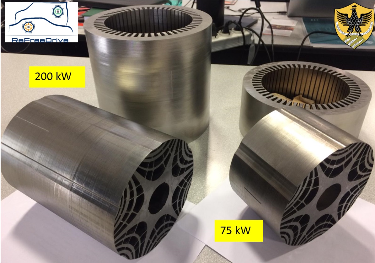
A lower power machine (75 kW peak power) has been scaled from the 200 kW design by only changing the stator winding and stack length in order to contain the manufacturing costs.
Two protoypes have been realized and Fig. 5 shows the stator and rotor cores of the 75 and 200 kW sizes.
5. Stator and rotor cores of the SynRM prototypes
The power electronic has been designed by R13 Technology (a University of L’Aquila spin-off) for a direct integration with the SynRM housing sharing the motor cooling system.
The powertrains (75 and 200 kW) will be tested in real driving conditions on a test bench and vehicle demonstrators.
by Marco Villani, University of L’Aquila, Dept. of Industrial and Information Engineering and Economics
ABOUT THE AUTHOR
Marco Villani, University of L’Aquila, Dept. of Industrial and Information Engineering and Economics
Marco Villani received the M.S. degree in electrical engineering from the University of L’Aquila, Italy, in 1985. He became an Assistant Professor of power converters, electrical machines, and drives in 1993. In 1990, he was Research Fellow at the University of Dresden, German, and in 1995 at the Nagasaki University, Nagasaki, Japan. In 1998 he cooperated in two SAVE projects concerning the “Energy efficiency improvements in threephase Induction Motors” and the “Barriers against energy efficient motor repair”. He has been involved in National Research Projects and took the responsibility of several research contracts between the University of L’Aquila and industrial partners. He is currently associate professor of Electrical Machines Design for the Master-level degree courses of Electrical Engineering at the University of L’Aquila. His research interests are focused on modeling and design of electrical machines, high efficiency induction motors, optimization techniques for the electrical machines design, Finite Element analysis of electric motors, design of PM synchronous motors and Reluctance motors for industrial, automotive and aerospace applications. He is author of more than 160 technical papers in scientific journals and conference proceedings.
3. Fault-tolerant motors for flap application (FA) and tail rotor drive (ETRD)
Fault-tolerant modular electric drives represent an already feasible solution to assure the reliability requisites of aeronautical applications. Prototypal studies and systems already operating in aircrafts confirm it. To understand better the characteristics and the specificities in this applicative ambit, we have talked about that with Professor Marco Tursini, ordinary professor of the Department of Industrial and Information Engineering and Economics at L’Aquila University.
Fault-tolerant electric drives arouse lively interest in aeronautical applications because they allow satisfying their strict reliability specifications. A modular design permits to obtain electric motors with high power density and high efficiency, as well as intrinsically fault-tolerant, without turning to the complete redundancy of the actuator.
Extending the approach to power electronics and to control, the use of electrical drives can be hypothesised not only in service motions but also in “safety critical” functions of aircrafts, such as primary flight controls.
To understand better the characteristics of multi-phase fault-tolerant drives in this operational ambit, the state-of- the-art and the new opportunities, we faced the issue with Professor Marco Tursini, ordinary professor of the Department of Industrial and Information Engineering and Economics at L’Aquila University, who reported as example some projects developed by his research team.
The added-value of modularity
In recent years we witness the growing use of electric drives in aircrafts, trend indicated by the English acronym MEA (More Electric Aircraft). The basic idea is replacing the conventional hydraulic and pneumatic actuation systems with more compact and lighter electric systems, to reduce consumptions and fuel costs, to allow longer flight routes and to decrease emissions.
The electric drives commonly used in industry cannot satisfy the reliability requisites demanded in aeronautics, especially in those functions on which depends the safety itself of the flight and of passengers.
These limits, connected with both the structure of motors and control electronics, have led researchers to explore new system architectures, able to guarantee the demanded reliability without turning to the complete redundancy, i.e. maintaining compactness and lightness features. «A possible solution – explains Professor Marco Tursini, Department of Industrial and Information Engineering and Economics at L’Aquila University – consists in considering the redundancy in terms of “phases” of the electric motor, directly in the design activity.
Such concept leads to the development of multiphase modular drives, able to satisfy the basic principles of the fault-tolerance of an electromechanical actuator, in other words the electric, magnetic and thermal insulation among phases».
We are hereunder illustrating some solutions developed on such principles by the research team of L’ Aquila University, coordinated by Professor Tursini, in the ambit of funded projects concerning the drive of flaps, of a cart lift system and of the tail rotor of a helicopter.
Examples of specific applications
The “flap actuator” (FA) is designed to move the flaps positioned on the trailing edge of aircrafts’ wings. Flaps are generally used just for some seconds during landing and take-offoperations and are “safety critical” systems of the aircraft because their failure affects the flight mission.
1. Electromechanical actuators for flap (FA) and cart lift system (CLS)
The CLS, Cart Lift System is instead a service lift used for the transport of foods and drinks between the hold and the passenger cabin in large aircrafts. Its failure affects passengers’ comfort and serenity and the same reliability specifications as for flaps are required. Both FA and CLS systems are based on a re-circulating ball screw device that translates the rotary motion to linear, whose mechanical view is illustrated in Figure 1.
The ETRD (Electrical Tail Rotor Drive) project, developed in the ambit of the European “Clean Sky” research programme, concerns instead helicopters with tail rotor drives of “Fenestron®” type, fully integrated into the terminal part of the tail beam, such as H 160 of Airbus Helicopters.
«In this case–Prof. Tursini underlines– the project target is the replacement of the current mechanical architecture, where the motion is taken by the main rotor and transmitted to the tail, with an electric motor directly coupled to the blades of the tail rotor, with the advantage, in addition to the system simplification, of guaranteeing a total decoupling between the speeds of the turbo-shaft engine and of the tail rotor, so notably widening the aircraft’s manoeuvre capability».
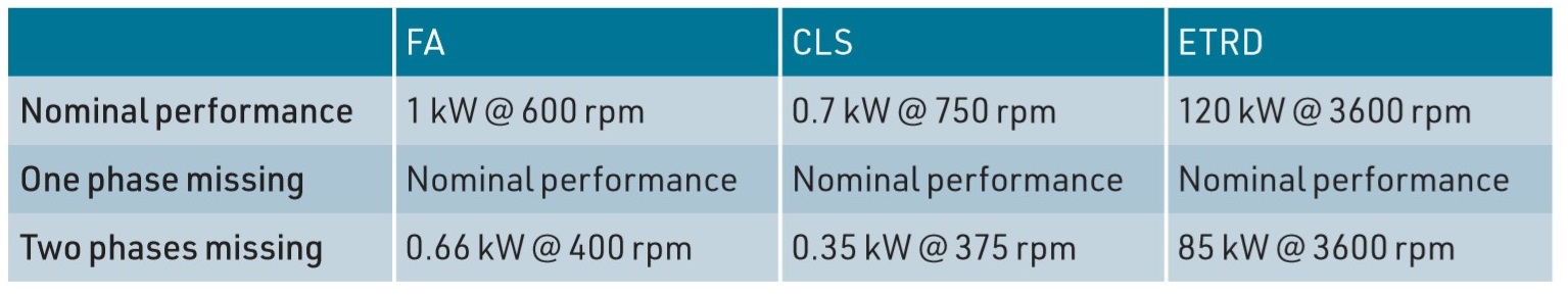
Fault-tolerance specifications impose that the loss of one phase owing to failure does not affect the capability of delivering the nominal power of the actuator, whereas with a further second loss it is possible to supply reduced power, decreasing torque or speed depending on applications, as we can deduce from Table 1.
Table 1 – fault-tolerance specifications
The fault-tolerant motor
The modular approach of fault-tolerant drives finds its natural implementation in switched reluctance or permanent magnet motors of “brushless DC” type (PM-BLDC).
The structure of the latter, preferred due to the higher achievable power densities, is illustrated in Figure 3.
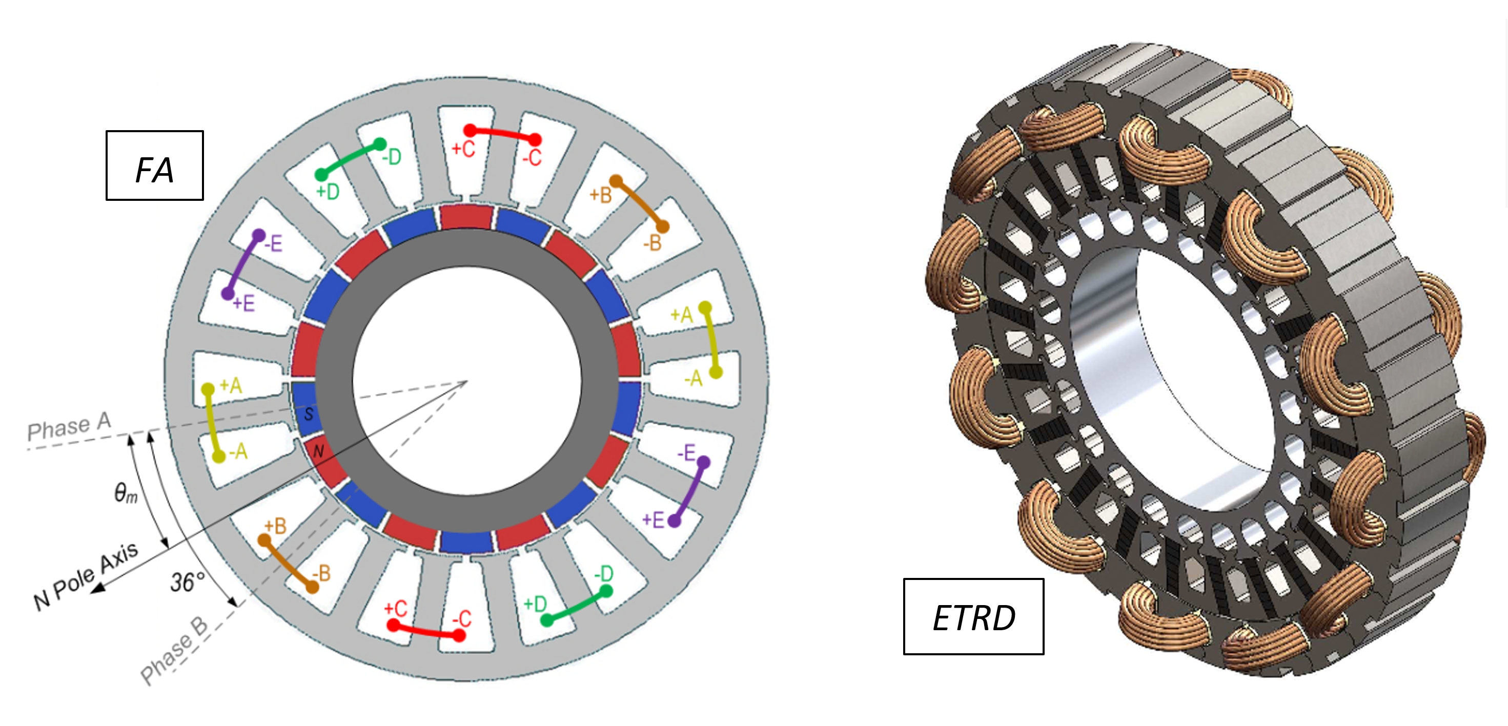
3. Fault-tolerant motors for flap application (FA) and tail rotor drive (ETRD)
«The electric independence –Professor Tursini highlights– is first of all implemented by powering the phases separately. Phase windings are made with coils arranged on protruding poles and by alternating wound and unwound poles. This implementation favours the failure reduction, through both the physical separation among the coils of the different phases and through the minimal overlap among the respective wirings. The arrangement on alternate poles features a low reciprocal inductance among phases, guaranteeing a substantial magnetic independence and a minimal thermal interaction. These engineering solutions allow avoiding the failure in one phase affects the others».
For the flap application, they have adopted the solution with five-phase PMBLDC motor, internal rotor, 18 magnets on the rotor and 20 stator slots.
«Each phase –Professor Tursini explains– consists of a pair of coils wound on opposite stator teeth, arranged at 180 mechanical degrees one another and connected in series.
The electromagnetic structure is sized to limit the netshort circuit current to phase terminals, with the rotor in motion at the highest speed. With the short circuit that is powered by the voltage induced by rotor magnets and generates overheating and braking torque. In the case of CLS and ETRD motors, we have adopted a similar solution with six independent phases».
The fault-tolerant drive
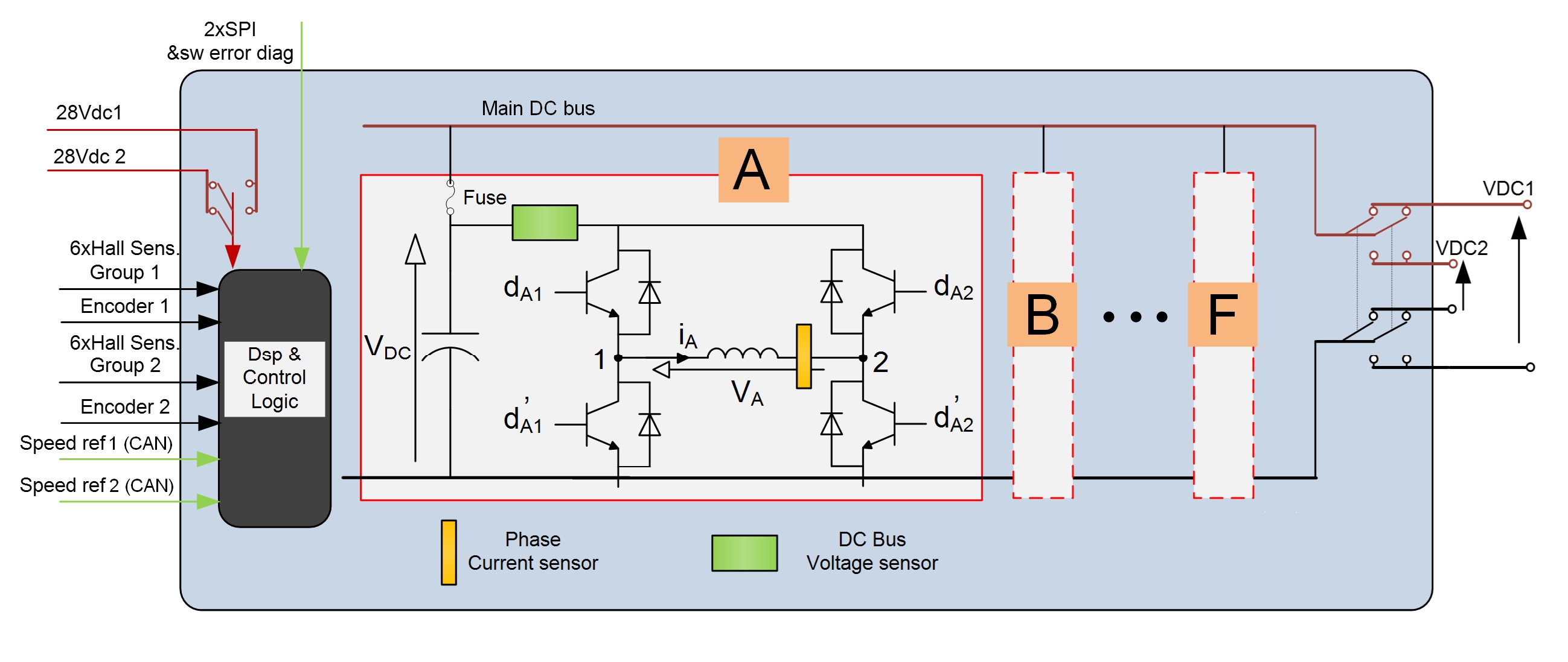
The modularity principle suggests that each phase is powered and controlled by a dedicated fully independent subsystem. Each subsystem includes the functions that can be directly referred to a single phase: a power bus, a power stage (inverter), current and voltage sensors and a control device (microcontroller), and it can operate autonomously from the others.
5. BLDC control of 5-phase motor
«The functions shared among the phases –Professor Tursini further points out– like the mechanical position sensor and primary power buses must be opportunely redundant to reach system reliability requisites». The current is controlled with a proportional-integral regulator (PI).
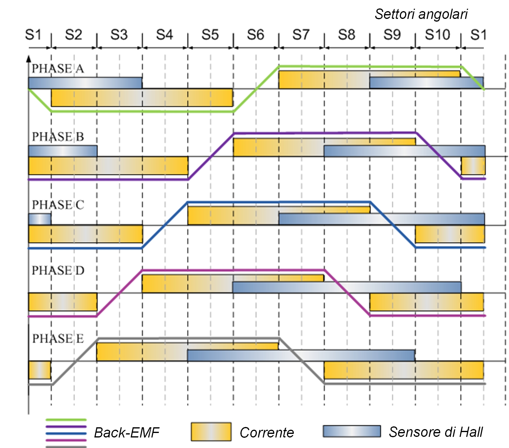
An orientation logic, enslaved to the position sensor, generates the current control. In PM-BLDC motors, the current is controlled in phase with the trapezoidal voltage induced by magnets (back-EMF), to generate constant torque, as shown in Figure 5.
Each phase shares in the overall torque with a proportional contribution to its own current. «An outer ring –Professor Tursini adds– adjusts the motor speed, drawn by the mechanical sensor, still with PI regulator.
A redundant communication bus allows phase microcontrollers to share the speed control, the position measurement and other useful information to equalize the control among phases».
The power stage of each module is composed by a single-phase inverter, as per Figure 6.
6. Fault-tolerant multi-phase inverter
In case of fault on a motor phase, the latter is disconnected by cutting off the power switches of the correspondent single-phase inverter.
«The short circuits on inverter branches –Professor Tursini adds – are primarily managed in hardware, detected by the drivers of power switches and reported to the microcontroller that provides for controlling the concerned branch in cut-off.
The short circuits persisting on the inverter and the short circuit on the levelling condenser are protected by the fuse cut-off at the stage input, which equally cuts out the phase but avoids the short circuit of the power DC bus».
Fault tolerance
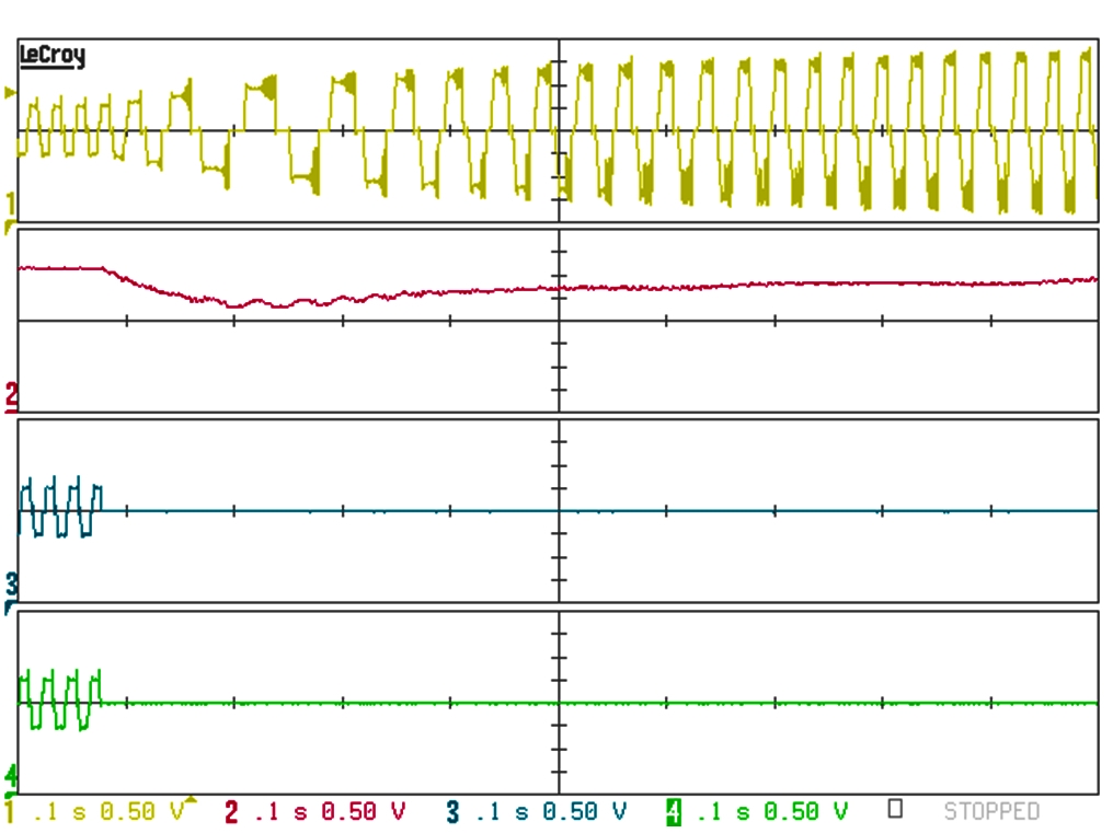
The architecture of the fault-tolerant drive allows the control adaptation in automatic in case of loss or cut-out of one or more phases caused for failure, as we can assess in Figure 7.
7. Control dynamics and the cutoff of 2 phases (5-phase motor for flap (FA) @300 rpm, 12.7 Nm)
«In such eventuality in fact –Professor Tursini highlights – we have a transient reduction of the produced torque and a consequent decrement of speed. The latter, surveyed by speed regulators, results in a rise of the current control for sound phases, which restores the value of the average produced torque to the pre-fault level and the speed to the controlled level».
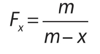
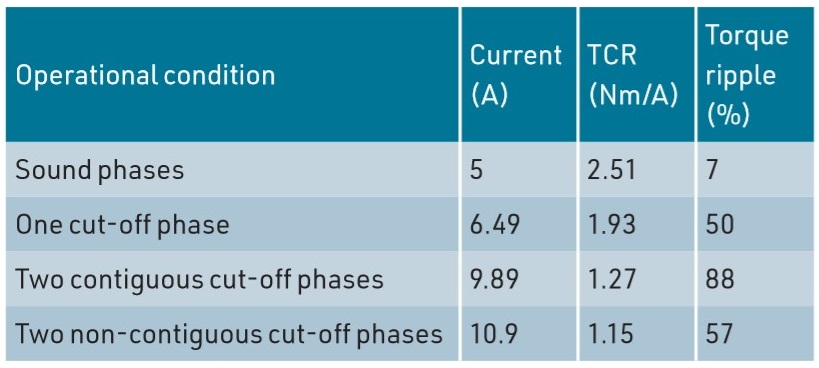
Owing to the loss of phases caused by failure, the torque ripple around the average value increases, hand in hand with the number of missing phases and with the adjacency of their angular arrangement in the motor, but this aspect is secondary in a “safety critical” system. «The fault-tolerant drive–Professor Tursini confirms – must then be sized fixing in the specifications the number of phases that can be lost and considering the overload of sound compensating phases». If we assume the torque/current relation as linear, the overload factor of a fault-tolerant motor is given by: Where m is the number of phases of the motor and x is the number of inactive phases (cut off) owing to faults or corrective fault actions. For a 5-phase motor, it is valid F1 = 1.25 and F2 = 1.66 respectively for one or two missing phases. «Actually –Professor Tursini adds–aeronautical actuators are sized to exploit magnetic circuits at best. Consequently, the active phases operate in conditions of high saturation in case of fault and the current overload is higher. The Finite Element electromagnetic analysis allows obtaining more accurate indications concerning this since the design phase».
Table 2 reports, as example, the results of the Finite Element analysis for the FA actuator, including the torque/current ratio (TCR) in the operation with sound phases and with fault.
Table 2 – motor performances for FA at nominal torque (12.5 Nm)
Guaranteed reliability requisites
What reported validates that modular fault-tolerant drives already represent an immediately feasible solution to guarantee the reliability requisites of aeronautical applications. Prototypal studies and systems already in use in aircrafts confirm it. «Compared to hydraulic and pneumatic systems –Professor Tursini ends– electric drives offer more user-friendliness in installation and maintenance, reduced overall dimensions and weights, hypothetically allowing the reduction of fuel consumption and of consequent emissions. This is a more and more central aspect in a globalized society taking care of environmental issues. Since 2008, the European Commission, in partnership with the major European aerospace industries, has promoted and funded “Clean Sky” Consortium, technological initiative for an “ecologically favourable” evolution of the air transport».
FOCUS ON RESEARCH
Marco Tursini was born in 1960 in L’Aquila province and graduated in Electrical Technology Engineering at L’Aquila University in 1987. In the same year, he started his scientific collaboration with L’Aquila University where he is currently Ordinary Professor of Power Converters, Electrical Machines and Drives and President of the Master Didactic Area Council in Electrical Engineering. In his career, he carried out research activity by the Swiss Federal Institute of Technology in Lausanne and by Nagasaki University.
Professor Marco Tursini, ordinary professor of the Department of Industrial and Information Engineering and Economics at L’Aquila University
Since the early Nineties, he has been manager of numerous research projects, in both industrial ambit (Texas Instruments, Indesit, Gefran, Denso, Umbra Cuscinetti) and in national funded projects (MIUR, PRIN, PON, Industria 2015) and European (Clean Sky). His interests concern the sector of electric machines and drives, with specific focus on modelling, simulation and control, “sensorless” drives, failure analysis and diagnostics, “realtime” simulation and rapid prototyping techniques. In this ambit, he is author of over 140 scientific publications. IEEE member and reviewer of numerous international journals and conferences, since 2011 he has been member of the Editorial Board of the international review “Electric Power Components & Systems”. In 2014 he promoted the birth of “R13 Technology” spinoff of L’Aquila University in the sector of industrial electronics, electric motors and drives, automation and measuring systems.
Conventional asynchronous motor (credits: Prof .Chiricozzi)
Conventional materials and technologies are by now reaching their performance limit. It is then clear the need of turning to a “revolutionary” synergy that succeeds in tracing a new frontier of development able to change the entire system of the electrical machine industry.
Electrical machines can still boast a notable improvement potential and, nevertheless, they are considered a quite mature technology. The constant improvement has been certainly achieved by using magnetic cores made of special steels, or with low magnetic loss, and high power density permanent magnets that provide low-loss excitation for machines, without however determining a revolutionary development. A real step forward, for a gradual change in the improvement of electrical machines’ performances, can occur only with the new rising materials, like for instance nanomaterials, also when combined with advanced technologies. A winning synergy can be established between new materials and forefront process technologies and it will undoubtedly be able to innovate the industry of electrical machines.
More efficiency and sustainability through nanoscale materials
The radical progresses that might substantially influence the efficiency and the performances of electrical machines require the introduction of new materials needed to replace the ones traditionally used.
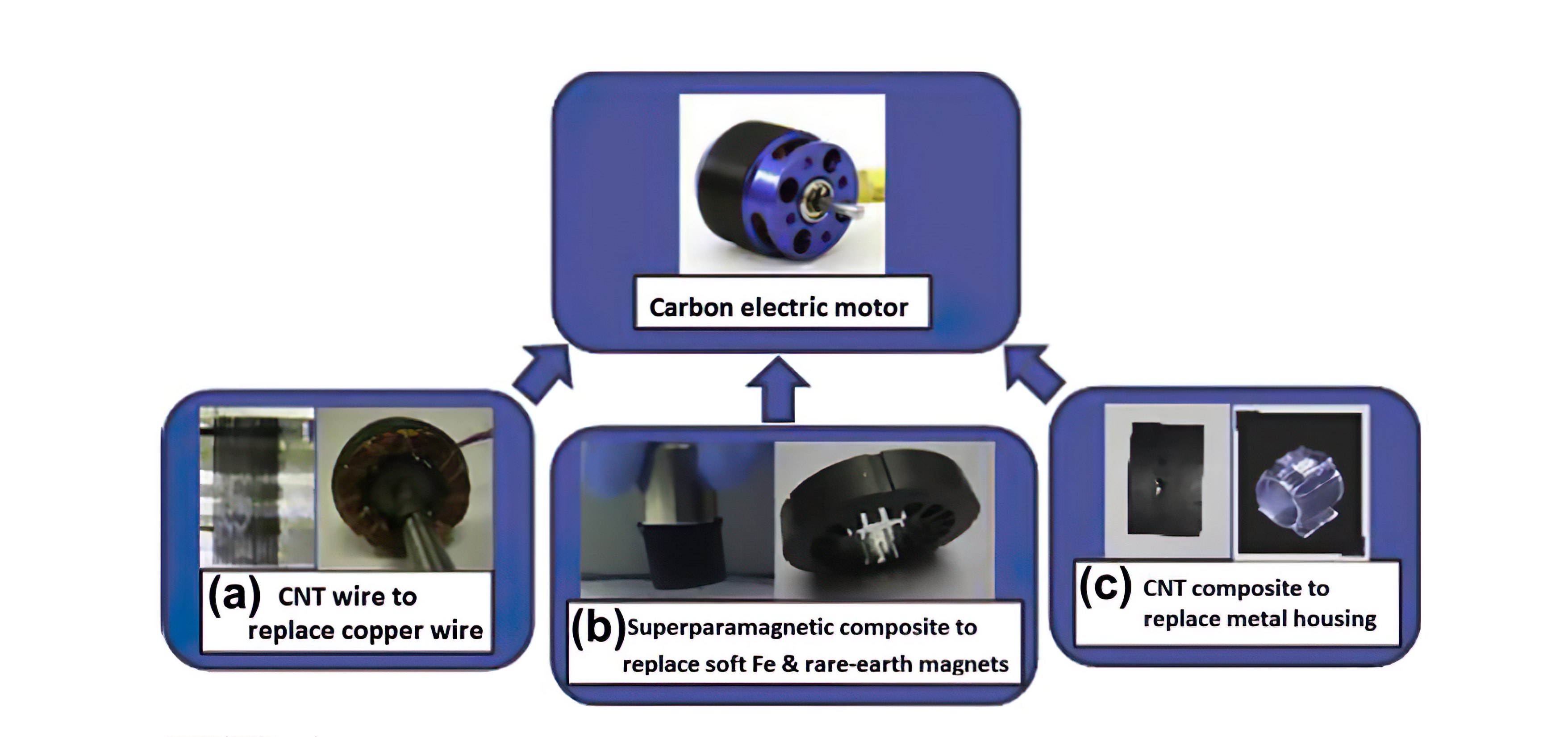
Multifunctional electromagnetic materials, such as carbon nanotubes, better known as CNT, and magnetic-core superparamagnetic nanoparticles are the new materials that can be used to replace respectively copper and iron in the conventional motor, and to design a light high-performance electric motor that can be a state-of-the-art example of future energy conversion devices.
The need of increasing the overall efficiency of the motor system, in fact, has never been so high. Owing to the increment of energy costs and the serious concerns for global CO2 emissions, reaching the highest possible efficiency of the motor system has become a fundamental priority. Motorized systems used by manufacturing industries play an important role in national energy profiles. The variety and the differentiation of future systems will be oriented towards a higher power density, with increasingly efficient and compact motors.
However, conventional materials and technologies are by now reaching their limit. Therefore, it is evident the need of a “revolutionary” technology that by will enabled just by turning to new materials: “nanomaterials” might change the entire system of the electric machine industry.
The materials used to make motors have not changed a lot since 1910 to today. Copper and iron are still used and rare earth magnets are exploited to obtain the nest performances. Today there is instead the possibility of using nanoscale materials to develop next-generation electric motors that are sustainable and more efficient. The future forefront electrical motor will require the integration of the fundamental research concerning the development of nanoscale materials with the re-engineering of the electromagnetic design of the motor itself, in order to overcome the limits of existing materials.
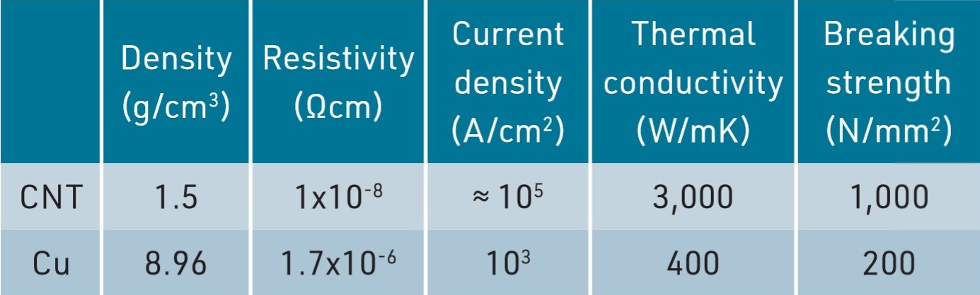
Carbon nanotubes, CNT, represent an extraordinary family of new materials characterized by as extraordinary electrical, thermal and mechanical properties.
Carbon nanotubes feature a density of 1.5 g/cm3 against 8.96 of copper; resistivity reaches 1 x 10⁻⁸ Ωcm, against 1.7 x 10⁻⁶ of copper; ≈ 105 A/cm2 is instead the current density, against 103 of copper. Thermal conductivity and breaking strength appear quite different, too: 3,000 W/mK and 1,000 N/mm2 for carbon nanotubes, against respectively 400 W/mK and N/mm2 of copper, as synthesized in the table (1).
Exploiting advantageously these intrinsic properties is based on the capability of systematically synthesizing, characterizing and integrating standardized materials into real devices. Therefore, almost the entire electric motor can be eventually manufactured with nanomaterials.
The main nanomaterials under development phase are the following:
1. Strong, light, electrically and thermally conductive CNT wire.
2. Superparamagnetic nanoparticles.
3. Hard magnetic nanoparticles.
4. Composites reinforced with carbon nanotubes.
Carbon nanotubes can replace the copper wire
The best carbon nanotubes have proven a conductivity widely exceeding best metals’. Therefore, the future windings implemented with such materials might have a double conductivity (100 MS/m) compared to current copper ones.
If we keep electrical machine design parameters unchanged and we replace only copper with future carbon nanotube yarns, we can reduce losses in windings by Joule effect to half of the machine’s current losses. Carbon nanotube yarns are much lighter than copper and more ecologic, too.
Therefore, the copper replacement with nanotube yarns should significantly decrease CO2 emissions connected with the production and the operation of electrical machines. Moreover, the sizes and the masses of the machine might be reduced and motors might also operate at significantly higher temperature than current ones.
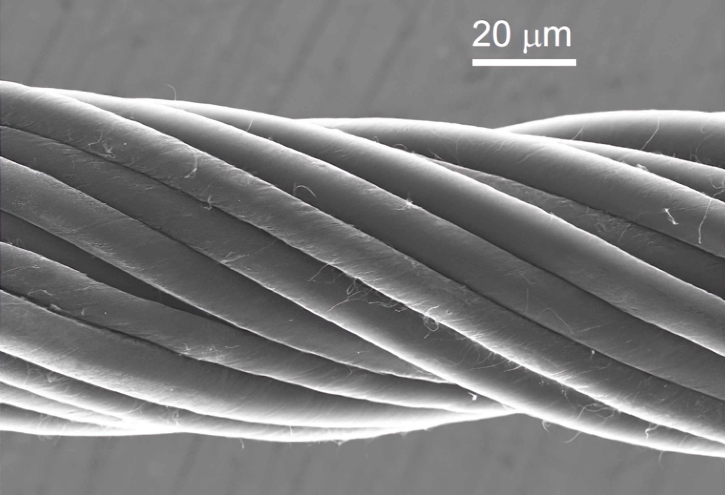
To facilitate the handling of CNT, carbon nanotubes are woven to form multifibre yarns like the one in the photo: twenty layers with diameter resembling human hair’s
In fact, a further highlight of CNT wire concerns the resistivity that decreases when the temperature rises (at environmental temperature, the resistivity temperature coefficient is negative, -0.2 x 10⁻³ /K), which is an advantage versus copper. Reducing the electric resistance of the nanotube yarn will be a future target to increase the power and to improve the efficiency of carbon motors.
Another advantage of CNT fibres consists in the fact they are constituted by very thin sub-conductors that should considerably limit the possibility of skin effects at the frequency of the electrical machine. Moreover, supposing future commercial CNT wires will be manufactured starting from multi-fibres that can be easily transposed, neither circulating currents are likely to appear. Both the skin effect and circulating currents can be very noxious in traditional high-current windings and result in higher resistance in AC.
Therefore, it should be possible to implement electrical machines with carbon windings that can work at higher operational temperatures than those today usually applied for their design. This is due to the fact there will be no increase of losses by Joule effect at the temperature rise.
Although it is not foreseen carbon nanotube conductors will soon replace copper ones, it is plausible to expect that in the short term CNT materials allow the creation and the development of new applications and new devices, wherever the same CNT wires can take advantage, compared to copper, in terms of lightness, flexibility, flexural strength, resistance to corrosion, high resistance and high modulus of elasticity, which is 103 kN/mm2.
Superparamagnetic nanoparticles, hard magnetic and CNT reinforced composites
As previously mentioned, among the main nanomaterials under development phase stand out also superparamagnetic nanoparticles and hard magnetic nanoparticles. The first, used in a polymeric matrix, produce an assembly of particles with low hysteresis and high saturation, then it is possible to manufacture a light-material magnetic core, which transports the same flux as the ferromagnetic one, or a higher one, and minimizes the loss of parasitic currents.
Hard magnetic nanoparticles are instead based on not critical, easily accessible, stable and easily recyclable 3D metals, like iron (Fe), Cobalt (Co) and Nickel (Ni), with a magnetization at high saturation and magnetic anisotropy.
Such nanoparticles can be used as constitutive elements for the manufacturing of sintered and alloyed permanent magnets, as replacement of permanent magnets currently used in electric motors containing critical rare earth elements at high cost. This new generation of permanent magnets can share in solving the sector dependence on rare earth metals, at the same time improving magnetic performances. This might be important for the development of electric cars based on rare earth elements for their powerful electric motors. Since nanocomposites feature better magnetic force/weigh ratios, the new devices, like electric motors, can be equipped with lighter magnets, so reducing their sizes and the weight as well. In that way, it would be possible to enhance the device performances while decreasing implementation costs, making the mass production much simpler.
Planning for the development of nanoscale materials and electric motor. CNT wire prototypes, magnetic material and CNT composite have been already produced in the UC Nanoworld laboratory
The last, but not least, family of nanomaterials under development phase includes the composites reinforced with carbon nanotubes. These materials will be increasingly available on trade with the rise of the production of CNT that, due to their intrinsic properties, will provide a much higher resistance than carbon nanotube fibres, in addition to a higher thermal conductivity.
Prerogatives, the latter, that will allow implementing the structure of the electric motor, the housing and the shaft, increasingly light and thermally conductive.
Hoping that progresses will be constantly confirmed in all four nanoparticle structures mentioned, there will be soon the conditions for the development of a “new generation of electrical motors”, which will be manufactured almost in their entirety with nanoscale and nanostructured materials.
New frontiers, trends and future developments
In today’s global more and more competitive market, the demands for higher power density, compact motors, lower costs and more reliability are driving the need of introducing an innovative approach to the use of new materials and advanced technologies, to allow the development of a new generation of electric machines and systems. The recent technological progresses in nanomaterials have opened new horizons and marked out the new frontiers for macroscopic applications.
The carbon nanotube wire, CNT, the magnetic core made with superparamagnetic nanoparticles and permanent magnets made with hard magnetic nanoparticles are new materials that can be used to replace respectively copper, iron and rare earth permanent magnets in conventional motors; this will permit to design a high-performance light electric motor that can be an example of a new generation of energy conversion devices. Other advantages of carbon motors undoubtedly concern also the fast acceleration, the high torque and the capability of operating at high temperatures and at higher speeds. The state-of-the-art motor must be then designed according to the synergy of the integration of different materials that exceed the limits of existing materials and exploit the properties of new materials.
The collaboration must reach an integration level where universities, designers and producers will work together to improve the understanding of the advantages and the challenges regarding the application of new materials and of advanced technologies, to allow the development of a new generation of electric motors that will play a fundamental role in industry and will envisage a new future for the society. I hope this challenge will be increasingly sustained and supported by potential stakeholders, so that Italy can release on the market the first electric motor made with nanomaterials and respective advanced technologies.
by Enzo Chiricozzi, Professor Emeritus of Electrical Machines University of L’Aquila
ABOUT THE AUTHOR
Enzo Chiricozzi, Professor Emeritus of Electrical Machines University of L’Aquila
Enzo Chiricozzi graduated in Electrotechnical Engineering at “La Sapienza” University in Rome. Full Professor of Electric Machines at the Faculty of Engineering of University of L’Aquila, he was appointed to various roles, like: President of the Graduation Course in Electric Engineering, Director of the Department of Electric Engineering, Dean of the Faculty of Engineering, Deputy Rector for the University Placement and the relationships with the labour world. In 2012, with decree by MIUR, Ministry of Education, University and Research, he received the conferment of the title of Professor Emeritus of University of L’Aquila. His research activity, developed in the scientific area of Electric Machines and Electric Drives, with in-depth study of various themes (torsional oscillations of big generating units; analysis of the dynamics of a heterogeneous group of asynchronous motors; the saturation problem in electric machines; high energy efficiency asynchronous motors; analysis of the dynamic operation of electric generators of synchronous and asynchronous type operated by wind motors; drives in DC and in AC controlled by microprocessors), has been acknowledged by the scientific community on a national and international scale.