
Completely composed by seaplanes, the Canadian airline Harbour transports over half million passengers yearly and it has recently announced it is going to convert all aircrafts of its property, equipping them with electric motors. Through an agreement with the company magniX that will supply propulsors, Harbour Air will therefore go down in history as one of the first fully electric airline companies.
The protagonist motor of this change is magni500 and the pioneer aircrafts of this installation are DHC-2 de Havilland Beaver. The motor develops 750 horsepower with an autonomy of more than one hour. Besides, considering that the vast majority of flights performed by Harbour Air last around half an hour, it is an excellent opportunity in both economic and environmental terms. Maintenance will be facilitated by a more user-friendly management of motors, with compulsory check cycles in longer times than with standard motors.
When will the transition from traditional to electric occur? It seems that it might even be accomplished by 2021, carrying out all twelve routes currently in operation.
In Canada 100% electric seaplanes

The innovative Wcs wind generator

It is worth saying: a wind of news is coming for the renewables of the future.
The Norwegian start-up Wind Catching Systems, established in 2017, has in fact designed an offshore wind turbine with an innovative floating wind power technology at competitive prices, which will make its debut in 2026.
The visual impact is impressive: the Windcatcher grid, a giant vertical net, over 324-metre high, whose meshes are hundreds of mini-wind turbines connected one another, arranged on a floating platform moored on the ocean floor.
The target is revolutionizing the technology for the offshore wind catching, a system competitive enough to operate without incentives, maximizing the energy production.
According to Wcs start-up, only one of these wind turbines might offer the double of the area exploited by the biggest standard wind turbines in the world and the smaller rotors can work much better even with wind speeds included between 40 and 43 km/h (27 mph). The overall effect, Wcs affirms, is the 500% rise of the yearly energy production.
Actually, each of these plants might replace five big single-turbine plants.
Wcs affirms these plants are ready for a service life of 50 years, compared to 30 years of a single large turbine.
Speaking of economic aspects, the plant is expected to supply offshore wind energy with the same cost as grid energy. In Norway, the average is currently about 86 Euros per megawatt hour and for their debut, in approximately 5 years, the price might even be around 80 Euros.
Measuring the efficiency of induction motors: what is the actual scenario?

The EU Regulation requires the measurement of efficiency for induction motors, as the surveillance task demanded to the different EU countries. Toward this goal, induction motors’ manufacturers and surveillance authorities should consider various issues related to measurement aspects, as the instrumentation to be adopted and the expression of measurement uncertainty.
by Edoardo Fiorucci, Dept. Industrial and Information Engineering and Economics, University of L’Aquila – Italy
The efficiency measurement is a critical issue in the induction motors market that concerns electric motors manufacturers, suppliers, consumers, and market surveillance authorities.
International Standards and Regulations
In 2009, the European Commission published the Regulation EC 640/2009) [1] concerning requirements for the eco-compatible design of electric motors.
This Regulation applies to single speed, three-phase 50 Hz or 50/60 Hz, squirrel cage induction motor, with 2, 4, and 6 poles, rated voltage up to 1 000 V, rated output power between 0,75 kW and 375 kW, continuous duty operation.
This Regulation does not apply to motors designed to operate wholly immersed in a liquid or integrated into a product (gear, pump, fan, or compressor), brake motors, and motors specifically designed to operate in particular environmental conditions.
This Regulation requires the measurement of efficiency for induction motors, as the surveillance task demanded to the different EU countries.
Toward this goal, induction motors’ manufacturers and surveillance authorities should consider various issues related to measurement aspects, as the instrumentation to be adopted and the expression of measurement uncertainty.
If we take a comprehensive look at the measurement procedures and at some basics of the measurement theory, we need to untangle ourselves among standard uncertainty, combined uncertainty, extended uncertainty, indirect and direct efficiency, and separation of losses tolerances of rated values.
Moreover, the standards seem to be not coordinated, so the operators can be in trouble if they aim at evaluating the efficiency with the related uncertainty, as required.
Two first remarks concerning [1] shall be made about uncertainty and tolerance.
In Annex II, the measurement uncertainty is considered, but only from a qualitative point of view: “…For the purposes of compliance and verification of compliance with the requirements of this Regulation, measurements and calculations shall be made using a reliable, accurate and reproducible method, which takes into account the generally recognised state-of-the-art methods, and whose results are deemed to be of low uncertainty, including methods set out in documents the reference numbers of which have been published for that purpose in the Official Journal of the European Union…”
The difference between the output mechanical power and the input electrical power is due to losses occurring in the motor. The determination of total losses shall be carried out by one of the following methods: measurement of total losses, or determination of separate losses for summation.
Tolerances for manufacturers are introduced in Annex III: “The authorities of the Member State shall test one single unit. The model shall be considered to comply with the provisions set out in this Regulation, if in the nominal motor efficiency (η), the losses (1-η) do not vary from the values set out in Annex I by more than 15 % on power range 0,75-150 kW and 10 % on power range > 150-375 kW…”
Although the effort in regulating the efficiency measurements, from an operative point of view, no numerical goals for the uncertainty are given, resulting in the issues we will discuss at the end of this paper.
The IE efficiency levels in [1] are in the IEC 60034-30-1:2014 Rotating electrical machines – Part 30-1: Efficiency classes of line operated AC motors (IE code) [2]. This standard establishes a set of limit efficiency values based on frequency, number of poles and motor power.
Let us consider the combined effects of [1] and [2], on the reference values for the efficiency, in a real scenario.
In Fig. 1, the IEC 60034-30-1 efficiency curves for 2-poles induction motors are depicted, for IE1, IE2 and IE3. The effect of the tolerances in [1] leads to the situation in Fig. 2a, with the effects of +/-(15/10) % uncertainty in power losses.
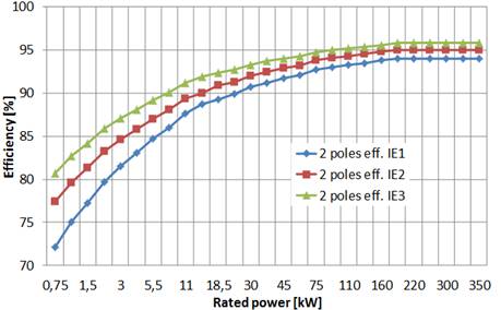
Each curve in Fig.1 should be replaced by a set of two curves, obtained by considering respectively 15 % (induction motors rated power up to and including 150 kW) and 10% (induction motors for rated power induction motors rated power above 150 kW) decrement and increment of the losses related to the IE efficiencies defined by IEC 60034-30-1, according to the rated power.
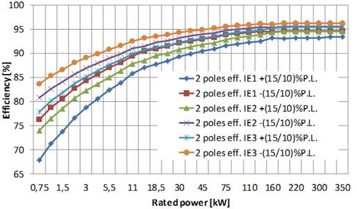
The obtained six curves are in Fig. 2a and Fig.2b. As a first remark, there are some overlaps because the IE2+(15/10)% curve is lower than IE1-(15/10)%curve, and the IE3+(15/10)%curve is lower than IE2-(15/10)% curve.
This issue could involve some difficulties in classifying an induction motor.
For example, the IE1 and IE2 efficiencies required for 5.5 kW 2 poles induction motors are 84.7% and 87%, respectively; the ranges depicted in Fig.2a are 82.40-86.99 for IE1 and 85.05-88.95 for IE2.
Let’s consider a rated efficiency of 86% declared by the manufacturer.
The considered motor can be simultaneously classified as IE1, because its efficiency is lower than % 86.99, but it can also be rated as IE2 because its efficiency is higher than 85.05%.
A similar problem can be raised for the overlaps of IE2 and IE3 curves. In Fig.2b the obtained curves for the higher rated power range are presented, as an expansion of Fig.2a.
Unfortunately, we have not considered the measurement uncertainty, yet.
Is it mandatory for the operators to evaluate the measurement uncertainty if they are measuring and then guaranteeing the rated efficiency of an induction motor?
Regarding the measurement laboratories, the general requirements for the competence, impartiality, and coherent operation of the laboratories are defined in the ISO / IEC 17025: 2017 [3] standard, which applies to all organizations that carry out laboratory activities but also to regulatory authorities and accreditation bodies.
It states that “testing laboratories shall have and shall apply procedures for estimating the uncertainty of measurement”.
So, we must refer to the uncertainty definition in the Guide ISO/IEC 99:2007, International vocabulary of metrology [4] as the “non-negative parameter characterizing the dispersion of the quantity values being attributed to a measurand, based on the information used.”
Coherently, the measurement result is a “set of quantity values being attributed to a measurand together with any other available relevant information”.
It is probably the most critical and neglected aspect in many experimental procedures in all the technical fields; each measurement result must be expressed as a set of data, not as a single point according to the Euclidean geometry.
Because of the impossibility of having zero uncertainty, we must define our results as a data set, whose width we tend to reduce according to the considered application, desired level of knowledge, budget, and available instrumentation.
In this scenario, the JCGM 100:2008 Evaluation of measurement data — Guide to the expression of uncertainty in measurement [5] is fully applicable because it establishes general rules for evaluating and expressing uncertainty in measurement intended to be applicable to a broad spectrum of measurement procedures.
All the above-mentioned recommendations and standards are to be considered together with the IEC 60034-2-1:2014 Rotating electrical machines – Part 2-1: Standard methods for determining losses and efficiency from tests (excluding machines for traction vehicles) [6]; it defines operatively the procedure for the measurement of efficiency.
The test methods are now grouped into preferred methods and methods for field or routine tests.
The preferred methods are presented as methods that allow low uncertainty; for a specific rating and type of machine, only one preferred method is currently defined.
The requirements related to the instrumentation are detailed and refined. Furthermore, the description of all the tests required for each method is explained, in the same sequence needed for the execution of the test itself, with flow diagrams that graphically show the sequence of tests.
As a general remark, it must be noticed an effort to model the effects of many experimental parameters in the evaluation of the different typologies of losses.
Some Experimental Results
In our Laboratory of Electrical Engineering at the University of L’Aquila, we have been testing several induction motors whose rated power is up to 15 kW (400 V, 50 Hz, TEFC, squirrel-cage), both for research and industrial applications since 1994 (Fig. 3).
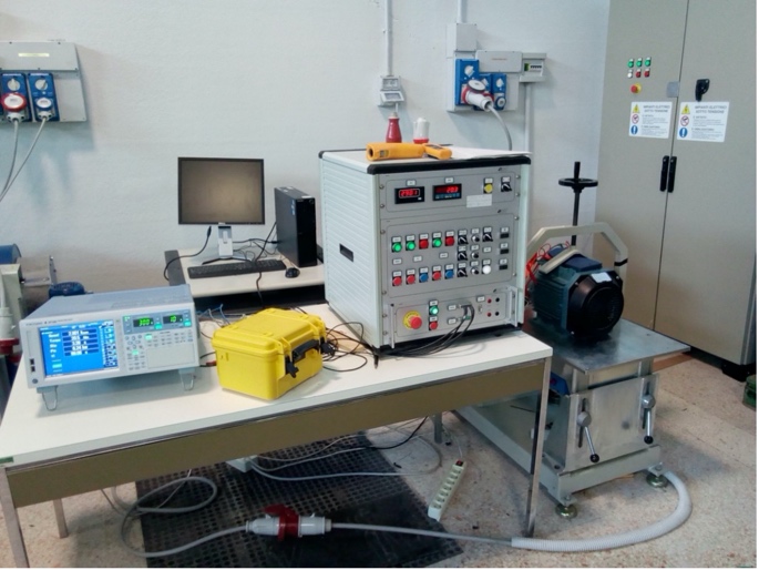
Today, our Laboratory is equipped with state-of-the-art instrumentation.
In detail, in this paper, some results about efficiency measurement according to the current version of the standards [5, 6] are presented.
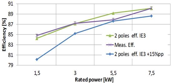
Fig. 4 shows the experimental testing results for IE3 – 2 poles induction motors; the accuracy achieved in efficiency measurement is ± 0,30 % by adopting high accuracy power analyzers and mechanical transducers.
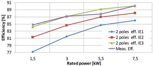
We can observe that only the 5.5 kW motor is below the IE3 efficiency; however, because of the allowed 15% uncertainty in power losses measurement, the manufacturer could correctly classify it as IE3 as suggested by Fig. 5.
This issue is more evident in Fig.6 for the 4-poles induction motors we tested; all of them are characterized by measured efficiency lower than the IE3 curve, which we have measured with experimental uncertainty of +/-0,40%.
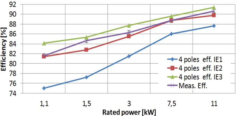
Nevertheless, although all of them are below the IE3 curve, they can be classified as IE3 because the manufacturer can take advantage of the allowed 15% uncertainty (Fig.7).

In other words, even if with a high accuracy measurement of efficiency, we demonstrate that an induction motor is below a rated IE efficiency value, the manufacturer could not be criticized because the EC Regulation N. 640/2009, Annex III allows him to perform the efficiency measurement with low accuracy.
Final Remarks and Conclusion
Finally, some remarks about legal issues can be raised in assigning an efficiency class for a measured efficiency.
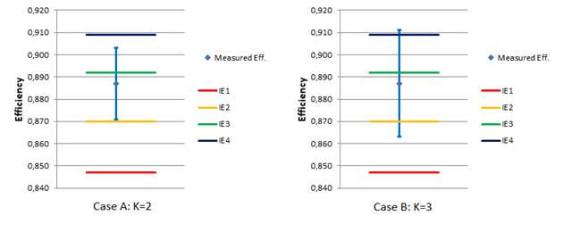
In Fig.8, what is the correct IE class, for a measured efficiency for the case A in which a coverage factor k=2 (95% confidence) is adopted according to the GUM [5]? The motor complies with IE2 requirements because all the data set is over IE2 level.
But I cannot exclude that it is IE3. If we extend the uncertainty, with k=3, (99% confidence), the data set covers 4 IE levels. So, which is the correct IE code for this motor?
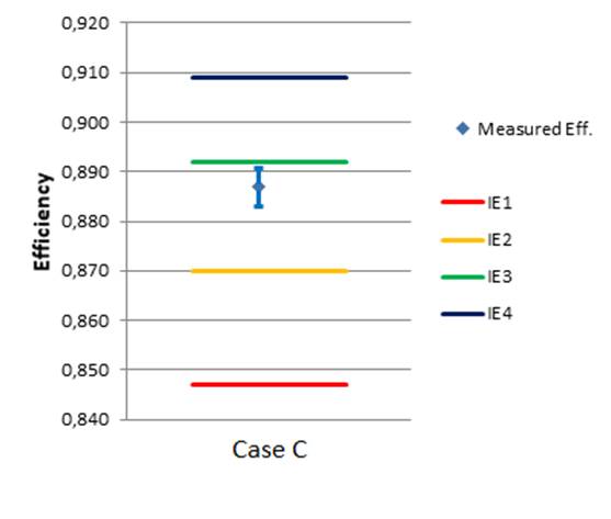
Maybe some additional suggestion of requirements in the international standards can be helpful, starting from the observation that the differences between two contiguous IE levels cannot be thinner than the measurement uncertainty; the desirable scenario is in Fig. 9.
Finally, how are two different data set to be considered if they are different? It is a typical situation in the measurement field. In this case, we must check if they are superimposable.
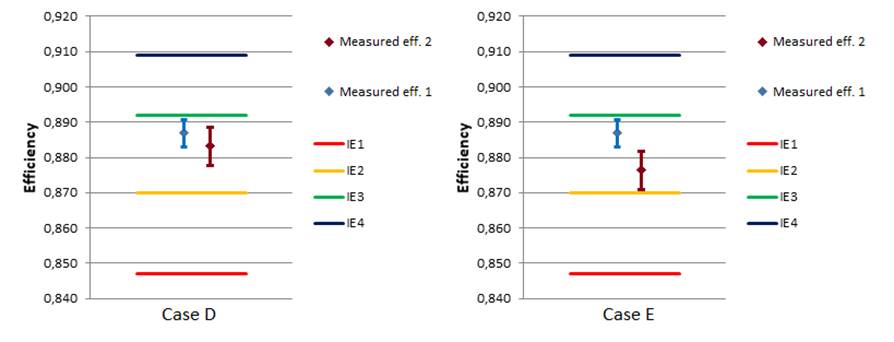
In Fig. 10, case D shows two sets that are compatible because they are partially superimposable.
Case E in Fig. 10 depicts how the measurements are not compatible, even if they lead to the same IE results because the motor complies IE2 level.
Some references that can be of interest to operators involved in this complex scenario are listed as [8-11].
References
[1] COMMISSION REGULATION (EC) No 640/2009 of 22 July 2009 implementing Directive 2005/32/EC of the European Parliament and of the Council with regard to eco-design requirements for electric motors.[2] IEC 60034-30-1:2014 Rotating electrical machines – Part 30-1: Efficiency classes of line operated AC motors (IE code).
[3] ISO/IEC GUIDE 99:2007 International vocabulary of metrology — Basic and general concepts and associated terms (VIM).
[4] ISO/IEC 17025:2017 General requirements for the competence of testing and calibration laboratories.
[5] SO/IEC Guide 98-3:2008 (JCGM/WG1/100) Uncertainty of measurement — Part 3: Guide to the expression of uncertainty in measurement (GUM:1995).
[6] IEC 60034-2-1:2014 Rotating electrical machines – Part 2-1: Standard methods for determining losses and efficiency from tests (excluding machines for traction vehicles).
[7] Power Analyzer Accuracy and Basic Uncertainty Calculator R511.xls, 2021, [online] Available: http://tmi.yokogawa.com/.
[8] Rajan, A., Kuang, Y.C., Ooi, M.P.-L., Demidenko, S.N. Measurement uncertainty evaluation: Could it help to improve engineering design? (2019) IEEE Instrumentation and Measurement Magazine, 22 (2), art. no. 8674631, pp. 27-32. DOI: 10.1109/MIM.2019.8674631.
[9] G. Bucci, F. Ciancetta, E. Fiorucci and A. Ometto, “Uncertainty Issues in Direct and Indirect Efficiency Determination for Three-Phase Induction Motors: Remarks About the IEC 60034-2-1 Standard,” in IEEE Transactions on Instrumentation and Measurement, vol. 65, no. 12, pp. 2701-2716, Dec. 2016. DOI: 10.1109/TIM.2016.2599459.
[10] Dubois, C., Leblond, L., Pou, J.-M., Ferrero, A. Covariance evaluation by means of uncertainty assessment (2016) IEEE Instrumentation and Measurement Magazine, 19 (6), art. no. 7777646, pp. 12-18. DOI: 10.1109/MIM.2016.7777646.
[11] Bucci, G., Ciancetta, F., Fiorucci, E., Mari, S., Segreto, M.A. The measurement of additional losses in induction motors: Discussion about the actually achievable uncertainty (2019) Energies, 13 (1), art. no. 78. DOI: 10.3390/en13010078.
Ford project that studies the electric motors of the future

In Germany, Ford with other partners has created a consortium to develop next-generation electric motors, to study new production processes.
The research project is called HaPiPro 2 and its target is developing new base products and processes that will play a protagonist role in the mass-production of components for electric vehicles, exploiting flexible, scalable and efficient methods.
The name HaPiPro 2 refers to the pin technology used in the wire winding inside electric motor groups: the Hairpin technology is a key innovation area in electric drive systems and the research will study precisely how to exploit its potential to allow the efficient manufacturing of several electric motor variants on a single production line.
The consortium includes, besides Ford, Thyssenkrupp System Engineering, Rwth and Engiro departments of 3D printing and product engineering of the University of Aachen, and electric motor experts.
The new research centre will be hosted inside Ford factory in Koln -Niehl, in Germany, “a unique advanced engineering platform for all companies, to research and to assess the future of electric motor manufacturing processes», as Gunnar Herrmann, executive President of Ford in Germany, described.
Electric motor: no more secrets about cooling system

Coiltech Electric Motor Talks are going on successfully, with the target – always hit – of strengthening the technical collaboration among experts in the specific sector. On May 26th 2021 it was the turn of Cooling Systems, crucial theme that remarkably influences electric motors’ efficiency. Quality speeches were delivered by speakers from different parts of the world, in the ambit of this joint initiative of University of L’Aquila and of Coiltech to promote the exchange of know-how between Coil Winding specialists and related fields.
The webinar was introduced, as usual, by Sebastian Kuester, CEO of Quickfairs, and Prof. Marco Villani, professor at University of L’Aquila and technical director of Electric Motor Engineering. «A critical element in the matter of an electric motor’s efficiency is characterized by inner components’ temperature».
Moreover, the evocative image to introduce the key topic of this session dedicated to Cooling Systems was particularly nice: a fine ice cream!
The first speech of the proceedings was cared by Mircea Popescu from Motor Design Ltd who cast the spotlights on “Advanced cooling systems for high power, torque density e-motors”, study carried out in synergy with Yew Chuan Chong and Husain Adam.
«To succeed in designing a better machine we need better materials like magnets, laminations and insulation, better design: for higher speed, and hairpin windings and, finally, better cooling like direct cooling, spray/jet cooling and rotor cooling».
Speaking of thermal management of electrical machines, the expert went into detail and he explained it is necessary to combine both passive cooling and active cooling, copper loss is a major loss component and the insulation materials restrict heat extraction within the slots wire insulation, impregnation resin and slot liner.
«More thermally conductive insulation materials are crucial to reduce the winding temperature rise and contact resistance between machine components due to imperfections can lead to significant temperature rise».
The advanced cooling systems of modern electrical machines include open ventilated cooling, housing water jacket, direct stator cooling and flooded stator cooling, oil spray cooling/oil jets/oil dripping cooling and supercritical CO2 cooling. A brief remark also on opened ventilated cooling that has been widely used in many transportations such as railway propulsion; airgap and ducts in the rotor are subjected to the effect of rotation.
«The housing water jacket is common cooling system used by automotive traction motors. It is simple and effective and ensures good cooling performance».
The speech by Mircea Popescu included also the direct stator cooling & flooded stator cooling. «It is important to meet the demand of electrical machines for aerospace industry. Front and rear regions were specifically designed to provide additional cooling to the end-windings by means of submerged oil jets. Segmented stators with concentrated winding are a common solution».
Towards the end of the speech, the public’s focus was addressed also on the comparison between housing cooling jacket and direct slot cooling and the analysis of oil spray cooling with various nozzles type and oil viscosity.
Manufacturing of Electric Motors for the Automotive Industry: cores manufacturing 24/06/2021 10.30-12.00
Manufacturing of Electric Motors for the Automotive Industry: winding and pm 23/06/2021 10.30-12.00
Insulating Materials 07/07/2021 10.30-12.00
Dr Fabio Campanini, Head of R&D of ELANTAS Europe spoke instead of “Thermal conductivity, with an outlook on electric motors’ encapsulation and future developments”. Focus on heat transfer methods. «Conduction is the main mood of heat transfer. It is the motion of a fluid driven by temperature differences across that fluid. It is the diffusion of thermal energy within one material or between materials in contact and energy is transmitted by the photons of the electromagnetic waves without the movement of mass». Besides, the expert showed some formulas on thermal conductivity, which is expressed in W/mK and he specified that the thermal management is a wide term and it includes various forms of heat transfer, like conduction, convection and radiation.
Another key question was “Why is it necessary to insulate an electrical device? The answer must be sought in the protection against moisture, protection against corrosive environments, improvement of electrical performance, mechanical protection versus vibrations and shock and easier handling.
Dr Campanini also spoke of the total encapsulation of electrical motors. «For this topic, the typical “wish list” includes low viscosity to allow good impregnation capability, good compromise between pot life and curing time, low CTE, good mechanical properties, very good electrical properties as a function of T, high thermal shock resistance, very good chemical resistance and high thermal conductivity».
Finally, zoom also on impact of toughness. The considerations in this ambit are that the thermal shock resistance is a key element too, difference design, dimensions and construction issue different challenges to the material and the mechanical stresses can be released with the creation of cracks.
«Cracks due to brittleness or ageing can be detrimental of thermal management and toughness of the system can be tailored working on the matrix and the use of special fillers».
10.30-12.00
Stefano Fortunati – CSM
Next Generation of Electrical Steel grades for Motor Applications
Prof. Luca Ferraris – Politecnico di Torino
Soft magnetic materials: new measurement methods and magnetic characterization
Benoît Clarenc – Aperam
Mechanical and magnetic capabilities and also facilitates the production process
Dr. Jürgen Klinkhammer – Magnet-Physik
Quality Control of Permanent Magnets
14.30-16.00
Koen Vervaeke – Magcam
Fast advanced inspection of PM rotors using magnetic field camera scanners
Simone Sgarzi – SPIN
From theory to practice and vice versa: how Spin nails final performance prediction thanks to its Lab
Cesare Tozzo & Gabriele Rosati – Comsol
Fitting B-H hysteresis data in time dependent and frequency domain FEM analyses
The engineer analysed how the thermal modelling of electric machines allows exploring various possible configurations for the cooling system, researching the optimal performance for and efficient cooling system, which can assure final product’s reliability.
The question that Pedram Nasab asked is “Why CAE?” «Because pluses are low cost, fast and reliable approach in evaluating the performance, run coupled analysis, enable designing compact products, check the critical working points like high-speed range and minimum battery voltage, and examine the non-ideal working conditions like short circuit test, cooling system failed test and general faulty condition».
The last technical contribution of the webinar was carried out by Philipp Bucher from LCD LaserCut who chose a very particular title: “Cool motor stacks for hot summer times”. The company’s primary competences are fastest possible shipment of prototypes and small series, high precision laser cutting technology and production of stacks and sub-assembly groups.
«Going one step further by 3D manufacturing. Added values of 3D additive manufacturing in terms of improved motor cooling integrated housing cooling, integrated shaft cooling, integrated end shields cooling, integrated power electronics cooling, integrated peripheral features and reduction of weight and material».
Finally, the highlights referred by Mr Bucher are best possible product based on integrated highly efficient cooling features and weight and material improvements, fast delivery time of complete assembly groups and only one involved party.
(by Lara Morandotti)
A new generation of high-performance e-motor, for braking systems and cars’ traction

Developing a new generation of high-performance electric motors, for both braking systems and cars’ traction, was the goal of Inproves pilot project, started in 2017, whose head company is Brembo, top player multinational in the production of systems for braking plants. Together with it, the partners eNovia, Mako-Shark, Magnenti Marelli, Motorsport, Peri, Milan Polytechnics, – Engineering and Energy Departments, MDQuadro, UTPVision and University of Bergamo have collaborated in the initiative.
We are in the ambit of the 2014-2020 operational regional programme, co-funded by Lombardy Region with European funds.
Inproves has provided for an integration of product and process for the implementation of road vehicles’ electric motors, to develop brushless electric motors (Permanent Magnet Machines-PMM) for both braking systems and for traction and energy recovery.
Such PMM are conceived simultaneously with the manufacturing process, based on Industry 4.0 paradigms, that is to say the complete digitalization of the production process, for the control and the management of plants, of processes and of logistic-productive flows.
Brembo and Marelli, with the support of Milan Polytechnics, have developed the mechanical and electromagnetic design of two different motor typologies for braking and traction systems.
Marelli has implemented a new high-efficiency traction motor, whereas Brembo has started the production of two motors’ prototypes for braking systems of different sizes, through a new digitalized assembling line, collaborating also with e-Novia, the Business Factory specialized in deep technologies, to develop a demonstrator of a new concept of integrated sensor for the control of the braking system. More in detail, concerning e-Novia, it is the design and testing of a magnetic sensor for measuring the rotor’s absolute position in a BLDC motor, with advantages in terms of assembling and performances.
«With INPROVES, today an ambitious challenging project is ending,” stated Alessandro Ciotti – Chief R&D Officer of Brembo, “which has involved the pre-industrial development of a new family of products and technical solutions in the ambit of the sustainable mobility of the future, whose priority targets are the adoption of more efficient, automated and connected vehicles».
Saietta: axial flux electric motor to electrify the world mobility

It is headquartered in the United Kingdom and it develops in pioneering way solutions for the automotive electrification and it is particularly in turmoil precisely for the great boom that the segment of electric vehicles is living, also due to the legislator’s contribution. We are speaking of Saietta, in search of new 250 collaborators and that has recently released its latest project: axial flux electric motor design, which combines both distributed windings with a yokeless stator.
Besides, the moment is particularly favourable: it has won a research contract through the Advanced Propulsion Center (APC) of the United Kingdom, but the witness by the chief executive officer of Saietta Group, Wicher Kist, a bit slows down enthusiasms: «We are ready for the future of transportation by stepping in with modern, lightweight electric motors as traditional internal combustion engines fuelled by petrol and diesel reach the end of the road. If the 2030 target is to be met, key decisions on future investment will need to be made quickly so companies like ours realize our full potential. That means more funding from UK government and quickly».
The company aims at a modular approach to its motors that are at the service of a broad range of vehicles, from scooters to trucks. Its first offer of commercial motors, for instance, AFT140, is optimized for the use of medium-size bikes and vehicles for last-mile deliveries, currently much more important solutions in terms of volumes in Asian markets rather than in Western ones. Precisely in this scenario, Saietta has recently announced a remarkable partnership agreement with Padmini VNA, one of the main automotive players in India.
The commercial agreement provides for Padmini collaboration with Saietta to develop new opportunities in the Indian market and renowned Indian two-wheel OEM players stand out among its customers, such as Hero MotorCorp, TVS, Bajaj Auto and Royal Enfield.
“Bodyless” batteries, integrated into the frame

It is known, the battery weight is one of the big burdens that hinders electric cars’ performances. Concerning this, the new frontier of the sector is the structural battery, a solution that might share in the direct implementation of a large part of the vehicle’s frame.
Among the experimentations in progress on this kind of “bodyless” batteries, a highly promising one belongs to the Swedish Chalmers University of Technology (introduced among the ten top technological discoveries in 2018), which precisely studies structural batteries based on carbon fibre. What is at stake? A battery that becomes integral part of the bearing structure of a vehicle, so making the currently known battery mass disappear.
To reach this innovation, Chalmers University researchers have developed some cells of carbon fibre, a compound that simultaneously acts as electrode, conductor and structural material. We know in fact that this material is very resistant in relation to its weight and that carbon can conduct electricity.
The present version of this battery is equipped with a carbon fibre anode and the cathode is made of aluminium coated by lithium and iron phosphate. The two electrodes are separated by a matrix fibreglass fabric that contains the electrolyte and contributes in the battery stiffness. The compromises in materials and the used chemistry nowadays provide an energy density of just 24 Wh/kg, then only 20% of the capacity of comparable batteries that are currently on trade. Hopes for the future are anyway good: a lighter vehicle will need less energy to travel the same kilometres and researchers have already outlined a course that will raise the energy density of these cells to 75 Wh/kg.
Next generation electric drivetrains for fully electric vehicles

The three EU-funded projects “ModulED”, “Drivemode” and “ReFreeDrive” will present their final project results in a joint workshop virtual event (to be taken on 16 april 2021 from 10:00 to 12:00).
The EU-funded projects will share and debate how they met the challenge set by the H2020 call “Next generation electric drivetrains for fully electric vehicles, focusing on high efficiency and low cost“.
 Focuses will be on functional system integration of electric machines; reduced need for rare earth magnets; integration of power electronics with battery charging functions, modular electric power train components.
The final event will be introduced by AVERE (Philippe Vangeel, Secretary General), short presentations of each project and panel discussion will follow. Wrap-up and final remarks will be by INEA – European Commission (Michal Klima, project officer).