
Thanks to appropriate numerical optimisation techniques, it is possible to drastically reduce the losses that originate in permanent magnets due to eddy currents, with a small reduction in the torque that can be developed by the machine. In the same way, it is possible to design machines with concentrated windings with combinations of number of slots and poles traditionally considered incompatible or not feasible in symmetrical form. This is confirmed by the studies carried out by Professor Alberto Tessarolo, University of Trieste, and by examples of how this approach can be of great application interest.
by Gianandrea Mazzola in collaboration with Professor Alberto Tessarolo,
University of Trieste

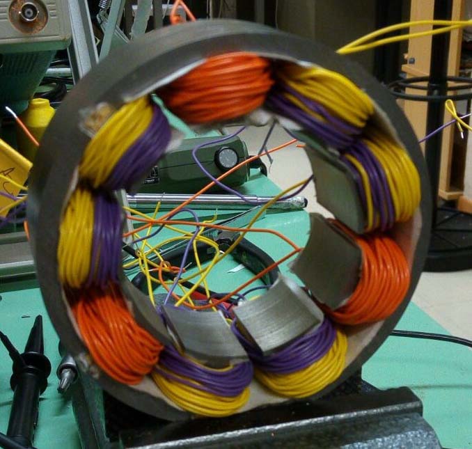
In the construction technology of modern electrical machines, the use of so-called “concentrated” or “wound tooth” stator windings is becoming more and more frequent, replacing, where possible, the more traditional “distributed” windings. The difference between the two types of windings can be appreciated by the examples shown in figure 1. It will be observed that the distributed winding consists of “ample” coils which embrace a relatively large portion and connect leads arranged in “distant” slots (figure 1a). Conversely, concentrated windings consist of “tooth coils”, i.e. coils each wound around a tooth in the stator’s magnetic core (figure 1b and figure 1c).


A drawback of concentrated windings is the fact that they, even when supplied with ideal currents, produce harmonic fields at the machine air gap which are capable of inducing losses due to eddy currents in permanent magnets and consequent overheating.
Moreover, it is not always possible to opt for concentrated windings. This is possible, in fact, at the state of the art, only for motors and permanent magnet generators in which the number of slots, indicated by Z, is similar (a little higher or a little lower) to the number of poles P.
In general, concentrated windings are usually considered feasible only if the number of slots Z and the number of poles P satisfy a precise algebraic relationship. More precisely, for the feasibility of winding, the quantity K, as shown in the following relation:
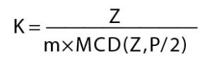
must be an integer number, having indicated by MCD (Z, P/2) the Maximum Common Divisor between Z and P/2. The above relation restricts the choice of the number of slots Z and poles P to a limited number of combinations (which we can define as “conventional combinations”). The limitation in question becomes particularly restrictive in the case of windings with more than three phases (m>3), as is often required to increase reliability. In the case of multi-phase windings, the scope of permissible poly-slot combinations is significantly reduced, thus significantly limiting the designer’s choice and precluding, in some cases, the adoption of wound tooth technology.
Large reduction of losses in the magnets, with small reduction in torque
In response to these critical issues, Professor Tessarolo has recently developed and proposed a methodology for the optimized design of concentrated windings, using multi-layer configurations.
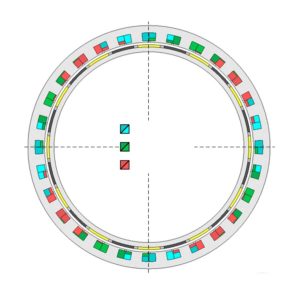
“Configurations in which – explains Professor Tessarolo – there can be several coils of different phases wound around the same tooth, as exemplified in figure 2, identifiable by different colours depending on the phase to which they belong.
The methodology, which is based on a particular algorithm of quadratic optimization, nevertheless easily implemented in widespread computing environments (such as Matlab), permits reducing some of the drawbacks of concentrated winding machines.
“In particular – observes Professor Tessarolo – this methodology makes it possible to reduce the risk of overheating of the magnets due to harmonic fields at the air gap and the problem of the limited number of combinations of project-acceptable poly-slots, especially in the case of a number of phases greater than 3.
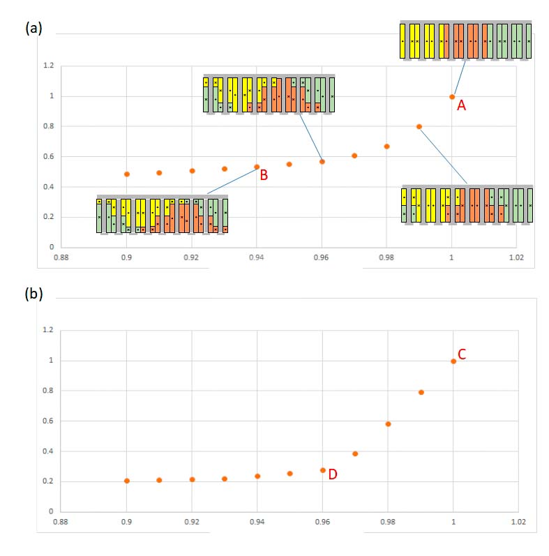
With regard to the reduction of ohmic losses in magnets, a multi-layer configuration optimized for wound tooth winding makes it possible to reduce the losses in magnets by up to 50%, at the price of a relatively limited reduction in the power developed by the machine. The potential for design optimization is exemplified in figure 3 for the combinations of 9 slots-8 poles and 12 slots-10 poles. The torque and losses of the magnets are normalized with respect to the value they assume for the traditional configuration (with a single coil for each tooth), represented by points A and C. Each point represents an optimized multi-layer design configuration.
“For example, in configuration B for the 9/8 machine, losses are reduced by about 50% at the expense of a 6% reduction in the nominal torque,” says Professor Tessarolo. “In the D configuration for the 12/10 machine, the losses in the magnets can be reduced by about 70% at the price of a drop of only 4% in the nominal torque.”
The optimization also extends the field of acceptable poly-slot combinations
The proposed optimisation method also permits extending the range of possible poly-slot combinations.
“In other words – underlines Professor Tessarolo – the method provides a symmetrical multi-layer configuration for a concentrated winding with a generic number of Z slots and P poles, even if Z and P are not such as to give a whole K in the above-mentioned equation”.
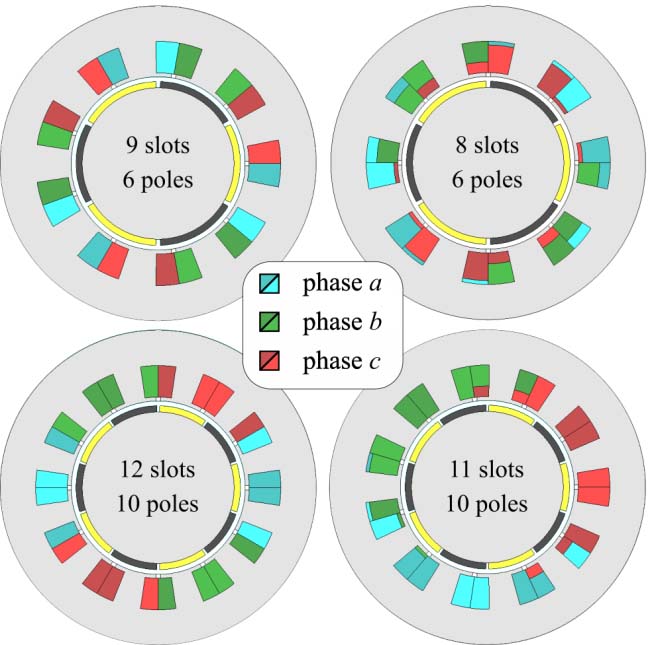
For example, figure 4 shows the cross-section of an 8-slot, 6-pole (unconventional) machine compared to the conventional 9-slot, 6-pole machine; similarly, the cross-section of an 11-slot, 10-pole (unconventional) machine is compared to the conventional 12-slot, 10-pole machine.
“From the comparison between conventional and non-conventional configurations – says Professor Tessarolo – it appears that the latter, in the face of a greater construction complication, in some cases show better performance. For example, the 9-slot and 6-pole machine in figure 4 has a high torque ripple which is about double that of the 8-slot and 6-pole machine. Or, to quote another example, the 11-slot and 10-pole machine has permanent-magnet losses around half those of the 12-slot and 10-pole machine”.
To give a more complete idea, the tables in figure 5 show a comparison between conventional (white cells) and non-conventional (grey cells) configurations in terms of winding factor and specific losses produced in the permanent magnets. It can be observed that some unconventional configurations have interesting and competitive values.

Operating benefits also for multi-phase machines
The possibility of using unconventional configurations can be particularly useful when designing multi-phase machines or machines consisting of several three-phase windings. This circumstance often occurs in applications that require continuity of service even in the event of a fault.
“For example – comments Professor Tessarolo – if you wanted to build a 12-phase machine, or with double three-phase winding, with eight poles, the conventional rules available in literature would force you to choose, to obtain a whole K from the above-mentioned report, a minimum number of 24 slots. It is clear that, for small machines, the use of Z equal to 24 could lead to unacceptable slot dimensions. The use of an optimized and unconventional multi-layer configuration can, in this case, be of help, making it possible to create a three-phase 8-pole, 9-slot double triad machine, as shown in figure 2”.
The prototype of this machine was also tested, recording the vacuum induced electromotive forces and then verifying the perfect electrical symmetry of the 9-phase winding, as shown in figure 6.
A further example of application is the 12-phase motor shown in figure 7, consisting of four three-phase windings offset by 90 degrees, each characterized by 7 slots and 6 poles. The choice of an unconventional winding in the case of what is shown in figure 7, was dictated by the need to have (for the maximum frequency allowed and the nominal speed) a total number of 24 poles, to be divided between the 4 independent units, of which the machine must consist for fault tolerance reasons. This resulted, for each unit, in a maximum number of 6 poles.
“The choice of 2 and 4 poles – underlines Professor Tessaroli – was not possible, as it led to excessive stator and rotor yoke thicknesses, such as to exceed the design dimensional constraints imposed on the radial dimensions. In this case, the project concerned the development of an electric outboard motor with integrated propeller, where space constraints were predominant. The number of poles for each unit was therefore fixed at 6, the choice of the number of slots such as to give an acceptable winding factor was between Z=9, Z=8 and Z=5, as shown in figure 5”.
The first (conventional) one was rejected because the torque ripple was too high. The only remaining options were therefore unconventional, i.e. 8 slots and 6 poles or 7 slots and 6 poles. The second was chosen because of its lower magnet losses and the almost zero torque ripple.
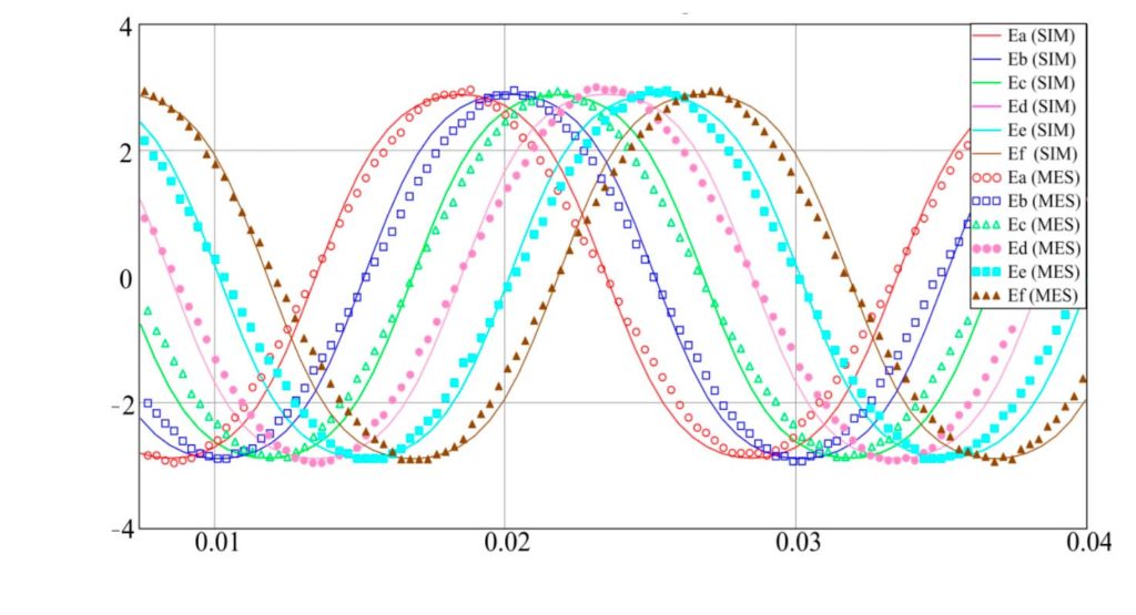
A prototype of the 7×4 slot and 6×4 pole three-phase quadruple winding machine was made (figure 8 a-b) and this was tested by connecting in parallel 2 of the 4 stator units and loading them respectively on a resistor star and on a diode rectifier bridge (figure 8 c-d). The results of the tests are shown in figure 9, where the waveforms recorded on the test bench are compared with those obtained by simulation of the machine with the finite element method in the time domain.
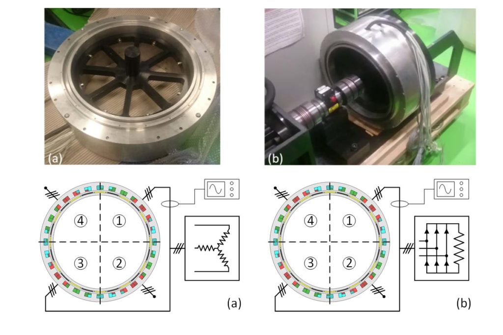
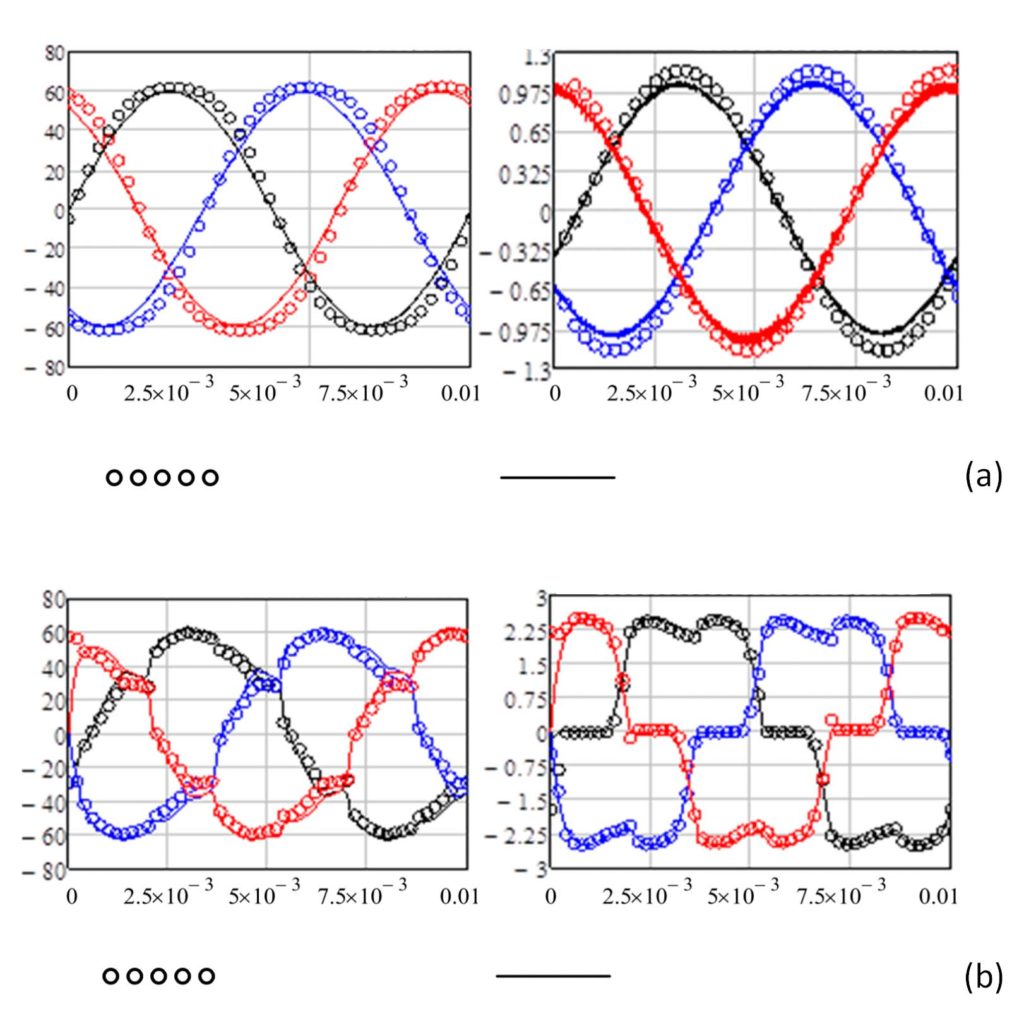
The results confirm the perfect symmetry of the machine and the excellent agreement between design forecasts and experimental behaviour. Similar waveforms, which do not show any unexpected phenomenon as a consequence of the choice of an unconventional winding, were also obtained by loading the other two machine units.
Professor Tessarolo concludes: “It can be said that the realization of concentrated electric windings, beyond traditional shapes and the classical limitations assumed for your project, have wide margins of optimization and extension. Provided that they are implemented on a multi-layer basis”.
It has been shown in these pages how, with appropriate numerical optimization techniques and the operating methodology proposed by Professor Tessarolo, it is possible to drastically reduce (even by more than 50%) the losses that originate in the permanent magnets due to eddy currents, with a small reduction in the torque which the machine is able to develop. It was also shown that, through similar optimization techniques, it is possible to design machines with concentrated windings with combinations of number of slots and poles traditionally considered incompatible or not feasible in symmetrical form. Finally, some application examples have been illustrated of how this can be of interest, especially (but not only) in the design of concentrated winding machines with more than three phases. It is therefore an operational approach and a methodology that, in fact, provides useful elements for greater freedom in design and execution.