
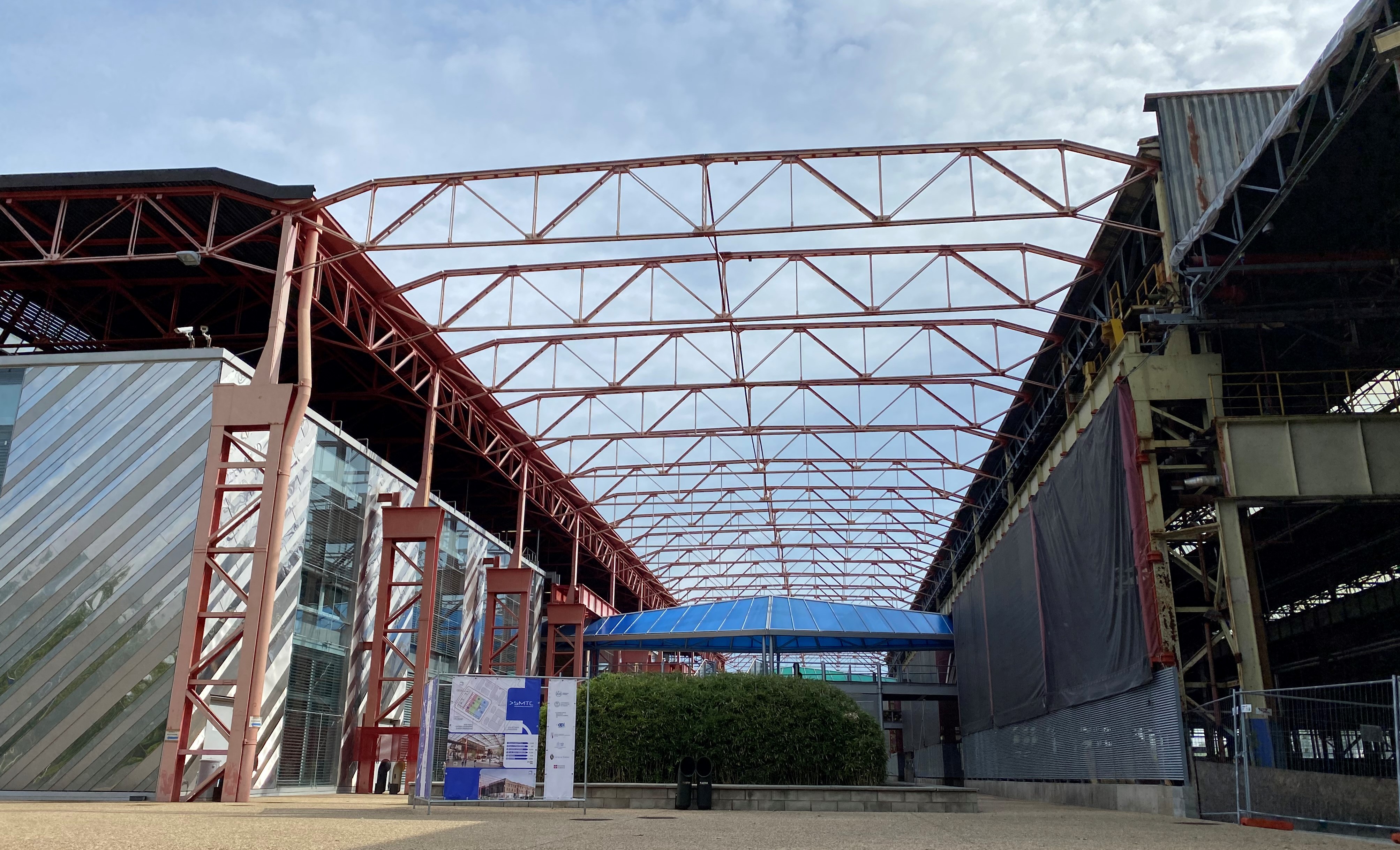
And in this future, the former Foundries in Modena are today at the core of an important redevelopment project that aims at implementing an enormous “innovation hub”, where electric motors will play a central role. Giovanni Franceschini, professor at the Engineering Faculty and already Dean of Unimore Engineering School, has explained the topicality of this area standing out for its great potentialities. «As president of the technical-scientific Committee of Democenter, my missions include seizing the technological challenge represented by the green mobility. So, the National Centre for the sustainable mobility, financed with NRRP resources, was born. Modena is involved in three specific ambits: the first concerns connectivity and autonomous-drive cars, of which Modena is national coordinator, the other two are linked with innovative propulsion, biofuels, hydrogen, fuel cells and electric traction: batteries, inverters and electric motors. The NRRP funds the purchase of equipment to create laboratories and to provide development systems. The idea is to succeed in making a part of the former Foundries a place where implementing these innovative laboratories for the sustainable mobility».
These spaces with academic propensity would represent an excellent opportunity for start-ups and spin offs. Moreover, the whole tertiary training might be moved here. With Democenter, for instance, we have recently started a master dedicated to companies’ employees with “more classic” mechanical education who need to learn how to operate in the new more electric world.
Forefront laboratories for the research on electric motors will be set up in Modena

Sustainable mobility: the excellence Italian National Pole was born

Last July 16th was presented the project of the National Pole of Sustainable Mobility and Manufacturing, also called SMTC, Sustainable Mobility Technology Center, which will be established in TNE spaces of Corso Settembrini 178 in Turin.
We, too, from Electric Motor Engineering were present, to be able to tell you at best this new Italian pride that exceeds a further border and involves more players of different nature: Turin Polytechnics, University, CIM 4.0, API, Turin Trade Chamber, Industrial Union, Piedmont Region and city of Turin.
The target is accompanying enterprises, especially small and medium-size ones, towards a course of innovation and training, giving them the possibility of using sophisticated tools, at disposal just with investments worth million Euros.
 The keyword is technological transfer, a possibility that can be implemented through the creation of a sound network and the contamination between technologies and competences, also due to the establishment of territorial companies, but not only, at the Pole’s.
Within 2023 this new excellence should become concrete, with Turin at the core of the capability of doing system, to full benefit of research, innovation and technological transfer to offer training services and activities.
All this is completed by a project of sustainable reorganization of an area still unused, feather in the cap of the automotive manufacturing, where the smartest companies will be attracted.
During the launch event, it was possible to visit the pilot lines that will be the technological core of the Pole: the Additive Manufacturing Pilot Line, the Laser Powder Bed fusion and Direct Energy Deposition.
Non-conventional design of concentrated windings

Thanks to appropriate numerical optimisation techniques, it is possible to drastically reduce the losses that originate in permanent magnets due to eddy currents, with a small reduction in the torque that can be developed by the machine. In the same way, it is possible to design machines with concentrated windings with combinations of number of slots and poles traditionally considered incompatible or not feasible in symmetrical form. This is confirmed by the studies carried out by Professor Alberto Tessarolo, University of Trieste, and by examples of how this approach can be of great application interest.
by Gianandrea Mazzola in collaboration with Professor Alberto Tessarolo,
University of Trieste

In the construction technology of modern electrical machines, the use of so-called “concentrated” or “wound tooth” stator windings is becoming more and more frequent, replacing, where possible, the more traditional “distributed” windings. The difference between the two types of windings can be appreciated by the examples shown in figure 1. It will be observed that the distributed winding consists of “ample” coils which embrace a relatively large portion and connect leads arranged in “distant” slots (figure 1a). Conversely, concentrated windings consist of “tooth coils”, i.e. coils each wound around a tooth in the stator’s magnetic core (figure 1b and figure 1c).


A drawback of concentrated windings is the fact that they, even when supplied with ideal currents, produce harmonic fields at the machine air gap which are capable of inducing losses due to eddy currents in permanent magnets and consequent overheating.
Moreover, it is not always possible to opt for concentrated windings. This is possible, in fact, at the state of the art, only for motors and permanent magnet generators in which the number of slots, indicated by Z, is similar (a little higher or a little lower) to the number of poles P.
In general, concentrated windings are usually considered feasible only if the number of slots Z and the number of poles P satisfy a precise algebraic relationship. More precisely, for the feasibility of winding, the quantity K, as shown in the following relation:
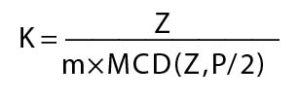
must be an integer number, having indicated by MCD (Z, P/2) the Maximum Common Divisor between Z and P/2. The above relation restricts the choice of the number of slots Z and poles P to a limited number of combinations (which we can define as “conventional combinations”). The limitation in question becomes particularly restrictive in the case of windings with more than three phases (m>3), as is often required to increase reliability. In the case of multi-phase windings, the scope of permissible poly-slot combinations is significantly reduced, thus significantly limiting the designer’s choice and precluding, in some cases, the adoption of wound tooth technology.
Large reduction of losses in the magnets, with small reduction in torque
In response to these critical issues, Professor Tessarolo has recently developed and proposed a methodology for the optimized design of concentrated windings, using multi-layer configurations.
“Configurations in which – explains Professor Tessarolo – there can be several coils of different phases wound around the same tooth, as exemplified in figure 2, identifiable by different colours depending on the phase to which they belong.
The methodology, which is based on a particular algorithm of quadratic optimization, nevertheless easily implemented in widespread computing environments (such as Matlab), permits reducing some of the drawbacks of concentrated winding machines.
“In particular – observes Professor Tessarolo – this methodology makes it possible to reduce the risk of overheating of the magnets due to harmonic fields at the air gap and the problem of the limited number of combinations of project-acceptable poly-slots, especially in the case of a number of phases greater than 3.
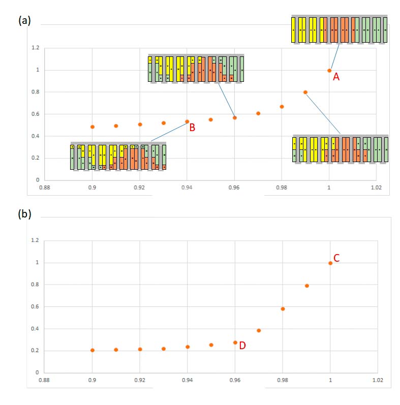
With regard to the reduction of ohmic losses in magnets, a multi-layer configuration optimized for wound tooth winding makes it possible to reduce the losses in magnets by up to 50%, at the price of a relatively limited reduction in the power developed by the machine. The potential for design optimization is exemplified in figure 3 for the combinations of 9 slots-8 poles and 12 slots-10 poles. The torque and losses of the magnets are normalized with respect to the value they assume for the traditional configuration (with a single coil for each tooth), represented by points A and C. Each point represents an optimized multi-layer design configuration.
“For example, in configuration B for the 9/8 machine, losses are reduced by about 50% at the expense of a 6% reduction in the nominal torque,” says Professor Tessarolo. “In the D configuration for the 12/10 machine, the losses in the magnets can be reduced by about 70% at the price of a drop of only 4% in the nominal torque.”
The optimization also extends the field of acceptable poly-slot combinations
The proposed optimisation method also permits extending the range of possible poly-slot combinations.
“In other words – underlines Professor Tessarolo – the method provides a symmetrical multi-layer configuration for a concentrated winding with a generic number of Z slots and P poles, even if Z and P are not such as to give a whole K in the above-mentioned equation”.
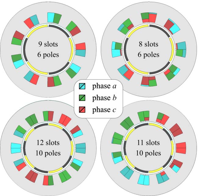
For example, figure 4 shows the cross-section of an 8-slot, 6-pole (unconventional) machine compared to the conventional 9-slot, 6-pole machine; similarly, the cross-section of an 11-slot, 10-pole (unconventional) machine is compared to the conventional 12-slot, 10-pole machine.
“From the comparison between conventional and non-conventional configurations – says Professor Tessarolo – it appears that the latter, in the face of a greater construction complication, in some cases show better performance. For example, the 9-slot and 6-pole machine in figure 4 has a high torque ripple which is about double that of the 8-slot and 6-pole machine. Or, to quote another example, the 11-slot and 10-pole machine has permanent-magnet losses around half those of the 12-slot and 10-pole machine”.
To give a more complete idea, the tables in figure 5 show a comparison between conventional (white cells) and non-conventional (grey cells) configurations in terms of winding factor and specific losses produced in the permanent magnets. It can be observed that some unconventional configurations have interesting and competitive values.

Operating benefits also for multi-phase machines
The possibility of using unconventional configurations can be particularly useful when designing multi-phase machines or machines consisting of several three-phase windings. This circumstance often occurs in applications that require continuity of service even in the event of a fault.
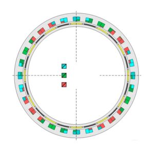
“For example – comments Professor Tessarolo – if you wanted to build a 12-phase machine, or with double three-phase winding, with eight poles, the conventional rules available in literature would force you to choose, to obtain a whole K from the above-mentioned report, a minimum number of 24 slots. It is clear that, for small machines, the use of Z equal to 24 could lead to unacceptable slot dimensions. The use of an optimized and unconventional multi-layer configuration can, in this case, be of help, making it possible to create a three-phase 8-pole, 9-slot double triad machine, as shown in figure 2”.
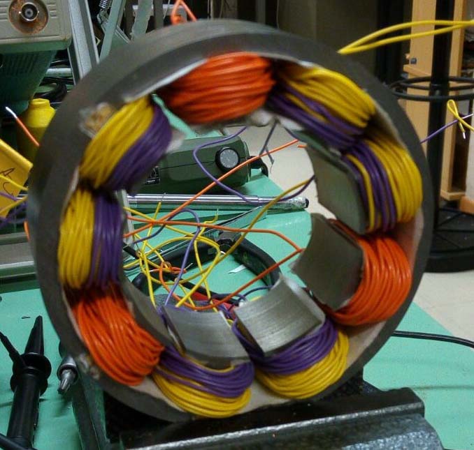
The prototype of this machine was also tested, recording the vacuum induced electromotive forces and then verifying the perfect electrical symmetry of the 9-phase winding, as shown in figure 6.
A further example of application is the 12-phase motor shown in figure 7, consisting of four three-phase windings offset by 90 degrees, each characterized by 7 slots and 6 poles. The choice of an unconventional winding in the case of what is shown in figure 7, was dictated by the need to have (for the maximum frequency allowed and the nominal speed) a total number of 24 poles, to be divided between the 4 independent units, of which the machine must consist for fault tolerance reasons. This resulted, for each unit, in a maximum number of 6 poles.
“The choice of 2 and 4 poles – underlines Professor Tessaroli – was not possible, as it led to excessive stator and rotor yoke thicknesses, such as to exceed the design dimensional constraints imposed on the radial dimensions. In this case, the project concerned the development of an electric outboard motor with integrated propeller, where space constraints were predominant. The number of poles for each unit was therefore fixed at 6, the choice of the number of slots such as to give an acceptable winding factor was between Z=9, Z=8 and Z=5, as shown in figure 5”.
The first (conventional) one was rejected because the torque ripple was too high. The only remaining options were therefore unconventional, i.e. 8 slots and 6 poles or 7 slots and 6 poles. The second was chosen because of its lower magnet losses and the almost zero torque ripple.
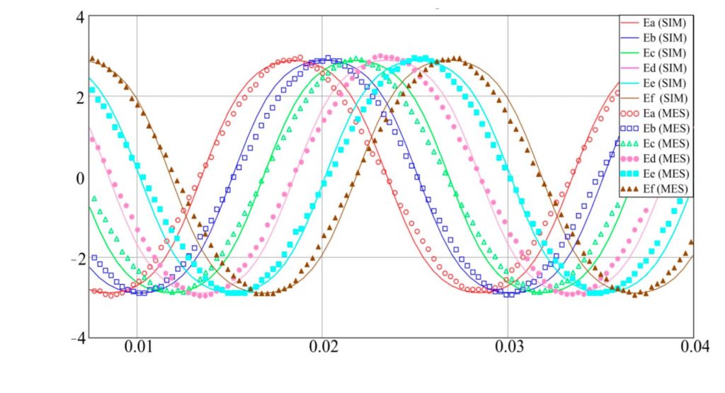
A prototype of the 7×4 slot and 6×4 pole three-phase quadruple winding machine was made (figure 8 a-b) and this was tested by connecting in parallel 2 of the 4 stator units and loading them respectively on a resistor star and on a diode rectifier bridge (figure 8 c-d). The results of the tests are shown in figure 9, where the waveforms recorded on the test bench are compared with those obtained by simulation of the machine with the finite element method in the time domain.
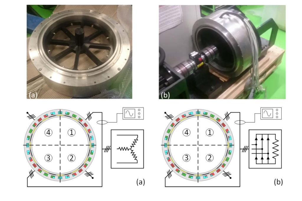
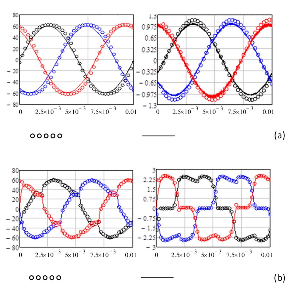
The results confirm the perfect symmetry of the machine and the excellent agreement between design forecasts and experimental behaviour. Similar waveforms, which do not show any unexpected phenomenon as a consequence of the choice of an unconventional winding, were also obtained by loading the other two machine units.
Professor Tessarolo concludes: “It can be said that the realization of concentrated electric windings, beyond traditional shapes and the classical limitations assumed for your project, have wide margins of optimization and extension. Provided that they are implemented on a multi-layer basis”.
It has been shown in these pages how, with appropriate numerical optimization techniques and the operating methodology proposed by Professor Tessarolo, it is possible to drastically reduce (even by more than 50%) the losses that originate in the permanent magnets due to eddy currents, with a small reduction in the torque which the machine is able to develop. It was also shown that, through similar optimization techniques, it is possible to design machines with concentrated windings with combinations of number of slots and poles traditionally considered incompatible or not feasible in symmetrical form. Finally, some application examples have been illustrated of how this can be of interest, especially (but not only) in the design of concentrated winding machines with more than three phases. It is therefore an operational approach and a methodology that, in fact, provides useful elements for greater freedom in design and execution.
Audi, powertrain with three electric motors

Audi’s will of further strengthening its electric expansion has led to the development of the S versions of Audi e-tron and Audi e-tron Sportback, which adopt three electric motors, two at the rear axle, able to supply an overall maximum power of 503 HP. It is an absolute premiere for mass-produced models.
The electric four-wheel drive avails itself of the innovative electric torque vectoring function with active variable distribution of the torque on the rear axle. Reactivity, performance and feeling while driving reach a new dimension.
503 HP and 973 Nm of torque allow shifting from 0 to 100 km/h in 4.5 seconds.
Will the autonomous-guide electric container ship be implemented?

The news of the manufacturing stop for Yara Birkeland, the first autonomous-guide electric container ship, arouses the debate about the green future of intermodal logistics. The matter was the transition of the transport from road to sea, reducing noise, pollution and fine dusts, with more safety of local viability.
The means, focus of the project started by Vard and Yara International in collaboration with Kongsberg Gruppen, which designs and develops autonomous-guide systems for military and civil vehicles, has captured the attention of the entire world. The “green” container ship is aimed at delivering goods in Norway through fiords, transporting products from Porsgrunn manufacturing site to Brevik and Larvik cities.
The reduction of nitrogen dioxide and carbon dioxide emissions that would occur in the region are equal to those generated by about 40,000 travels per year of trucks.
The loading capacity of Yara Birkeland, which will cover a course of approximately 40 miles at a maximum speed of 10 knots, is equal to 150 TEU. Besides, also the loading and unloading phase will be sustainable: it will occur with electric equipment.
In the opinion of Svein Tore Holsether, president and managing director of Yara, “this new autonomous battery container ship accomplishes the transition of the transport from road to sea, reducing noise and fine dusts and improving the safety of local viability.”
The means was expected to be ready in the first months of 2020, becoming at fully autonomous guide in 2022, but Pandemic has postponed everything. Let us see …
Volvo invests in a new laboratory in Shanghai

To design and to manufacture in-house electric motors for the next car generation, Volvo Cars has inaugurated in Shanghai, in China, a new laboratory precisely dedicated to electric propulsion systems. This structure, in operation since last month, joins the unit that constantly develops electric motors in Gothenburg, Sweden, and modern laboratories for batteries in China and Sweden.
«Through in-house design and development processes, we will be able to perfect our electric motors, reaching higher and higher qualitative levels. Constantly ameliorating the overall performance levels of propulsion systems in terms of energy efficiency and comfort, we create an electric drive experience that exclusively identifies Volvo brand» – stated Henrik Green, Chief Technology Officer of Volvo Cars.
The laboratory activity will focus on the development of electric motors for applications in purely electric and hybrid cars based on the modular architecture for SPA 2 vehicles. The future of the brand is well outlined: the target is rising to 50% the share of fully electric models out of the total of global sales by 2025, with the remaining part constituted by hybrid models.
University of Nottingham starts electric motor consultancy

The University of Nottingham has created a business unit for the industrialisation of electrical motors and drive systems, claiming that it is the first UK institution to establish an independent business unit for the industrialisation of electrical motors and drive systems.
Nottingham Drive Specialist Services (NDSS) will provide «bespoke development, manufacturing and testing of electrical motors and drives to support the industrialisation of power electronic converters, electrical machines and drives from design through to manufacture and testing», according to the university.
It is based at the recently opened Power Electronics and Machines Centre (PEMC) and has access to more than £20m of equipment. Funding has come from Research England, Getting Building Fund, D2N2, the Wolfson Foundation and the Driving the Electric Revolution Industrialisation Centre. «Over the past 25 years, we have built up a store of intellectual property on this subject area and making this available for companies to benefit from is a key part of what we are doing to support the drive towards electrification and developing the UK supply chain» said NDSS general manager Hitendra Hirani.
The facilities include Test cells: 2MW, 5MW, 500kW altitude environmental, 120,000rpm; propulsion; aircraft generator and actuator test; Characterisation: magnetic materials and insulation; 3MVA PSU and energy storage emulation and Specialist coil winding: Needle (concentrated and distributed stators), Litz, flat conductor, hairpin (continuous and variable cross-section).
Hitachi enters the automotive world

To face the growing market of the sustainable mobility in the United States, the Japanese company Hitachi has decided entering the segment of electric motors for battery vehicles.
Last August 19th, for this purpose, they have established Hitachi Automotive Electric Motor Systems America, with Shingo Nakamura as President.
The location where electric motors will be produced is in Kentucky, exploiting already existing offices and factories in Berea city, covering almost 260,000 square metres.
Manufacturing is expected to start in 2022.
Hpe Coxa, artificial intelligence laboratories to develop electric motors

About two years ago Hpe Coxa, company specialized in services of engineering, design and precision manufacturing for the sectors of automotive, motorsport, automation, aerospace and defence, inaugurated in Modena the two E LAB and Ai LAB laboratories that establish the company’s collaboration with the Universities of Bologna and Modena in the most advanced technological fields. In particular, E LAB, in collaboration with the University of Bologna and UniMoRe, has made students work at the design, engineering and implementation of an electric motor, supervised by “senior” engineers: in just nine months they have given birth to a unique item, the “demonstrator”. Today, they go on innovating in that direction and in Modena the excellence centre for the Artificial Intelligence is established, due to the collaboration between Hewlett Packard Enterprise and HPE COXA, further raising the bar of the development of solutions, including electric motors. This synergy will lead them to explore together the new opportunities of the data age for the industrial sector.
Combining design skills and competences that range from high-performance mechanical engineering to the most recent IT technologies, the two partners will develop a common ecosystem committed to innovation and based on Open Innovation principles.