

When car manufacturer Daimler formed a joint company in 2011 with Bosch, the world’s leading automotive supplier, the synergy between the two companies was obvious.
The joint company, EM-motive GmbH, combines Daimler’s expertise in fuel cells and batteries with Bosch’s knowledge of the development and production of electric motors to design and manufacture electric traction motors for electric and hybrid vehicles.
Because the motors are designed to be modular, they can be adapted to fit a variety of vehicle classes and meet specifications for many different vehicles.
Since 2012, the company has manufactured more than 300,000 e-motors for client companies throughout Europe.
Even with this combined expertise, manufacturing a modular engine is complex and challenging. In addition to the main engineering constraints (cost, mounting space for the motor, cooling and inverter-specific properties), the customer-based requirements for each type of engine cover a wide breadth of individual physical domains:
-Thermodynamics: coolant flow rate and temperature, environmental temperatures, as well as winding and magnetic temperatures
-Structural mechanics: mounting space, torque, power, speed, tolerances to other parts and forces on bearings
-Electrical engineering: voltage, current, inverter-specific properties
-Efficiency and acoustics: airborne and structure-borne noise
To make the challenge even greater, all of the parameters to be optimized have to be considered simultaneously. Other factors must also be taken into account: noise, vibration and harshness (NVH); safety; and the cost of the engine.
The engineers at EM-motive realized that, in such an interactive environment, a “classic” component development system, where rigid specifications for each component are designed separately and then assembled, was no longer possible.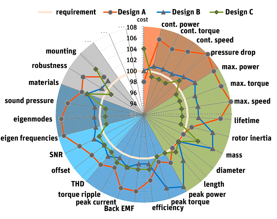
Instead, the company developed a design workflow that incorporated simulation throughout to account for the dynamic interactions between the components, as well as all the necessary parameters to determine optimal solutions and ensure design robustness. The parametric workflow to support sensitivity analysis, design optimization and design robustness evaluation includes ANSYS simulation software and other software tools, and was built and hosted in ANSYS optiSLang.
These workflows help EM-motive to develop electric motors within challenging time and cost requirements, as well as resolve customized design challenges, such as a late-stage customer requirement change for an engine design.
As an example, a customer requested that the maximum speed for a particular engine needed to be increased by 1,000 revolutions per minute (rpm). The centrifugal forces of the accelerated speed, however, would cause the rotor design to fail.
The engineers could increase the bridge thickness of the pockets for the magnets that are punched into the rotor lamination to withstand stress caused by the higher centrifugal forces. However, this would increase the flux leakage in the rotor itself, causing reduced torque and power.
An option to address this reduction is to increase the current in the windings (but only if higher current is available from the battery and electronics system).
This solution would intensify losses and reduce efficiency, and was not acceptable to the customer. It was therefore necessary to redesign the entire engine to comply with all requirements.
Fortunately, the EM-motive simulation workflow can be flexibly adapted to analyze the requirements for a specific engine, simulate all the dynamic interactions between the components, and present the customer with a solid understanding of the trade-offs for each design decision.
The workflow provides the foundation to determine the best compromise for often contradictory goals.
A workflow for digital exploration
During the procurement phase, using ANSYS optiSLang workflow connected to CAD and employing specialized electromagnetic–thermal software, the design engineers have the freedom to explore possible variations and their tolerances to fulfill customer requirements. They can then provide a fast answer so the customer will know if the requirements can be met with available motors or if new motor development is needed.
Through a set of iterative phases in which additional requirements are added, a new motor is designed and optimized using ANSYS simulation software in all the relevant physical domains. A shared interface with the ANSYS Simplorer systems simulator helps them analyze the influence of power electronics on the motor.
Because there is a bidirectional interface between ANSYS DesignModeler and the CAD system, engineers can create parameterized models of auxiliary geometries, such as the housing, and integrate them into the system design. The ANSYS tools allow the designers to use the results of one type of simulation as a boundary condition for another.
They can then use forces from an electromagnetic simulation with ANSYS Maxwell as initial data for a structural mechanical simulation with ANSYS Mechanical. Using the various ANSYS tools integrated through ANSYS Workbench makes it possible to create a completely coupled simulation of the electromagnetic, mechanical, thermodynamic and acoustic domains.
With these parametric workflows in place, all important physical domain sensitivity studies within the relevant design space, as well as tolerance determination, can be conducted.
The engineers can add further optimization loops, but because of the conflicting character of many discipline goals and constraints, and because of the need to quickly check the motor behavior on a systems-simulation level, reduced-order models (ROMs) must be extracted. Using the integrated equivalent circuit extraction (ECE) toolkit within ANSYS Maxwell or ANSYS optiSLang’s data-based ROM generation, the team can extract reduced models for an overall system simulation.
Systems modeling
These reduced-order models can be coupled in ANSYS Simplorer to create a complete system simulation. Again a parametric workflow is built within optiSLang and, optionally, other third-party models can be integrated, such as a transmission model or a complete vehicle model. At this point, the engineers might perform a system optimization loop to analyze the interactions between the components by varying parameters such as those for the controller.
Finally, to make the model interchangeable with additional engine components designed by outside parties, the designers use the industry-standard functional mock-up interface (FMI) to create models of the individual components, called functional mock-up units (FMUs). These FMUs are created with third-party software and can easily be exchanged while maintaining IP confidentiality: since they contain only standardized inputs and outputs, the product-specific know-how is only accessible to the manufacturer.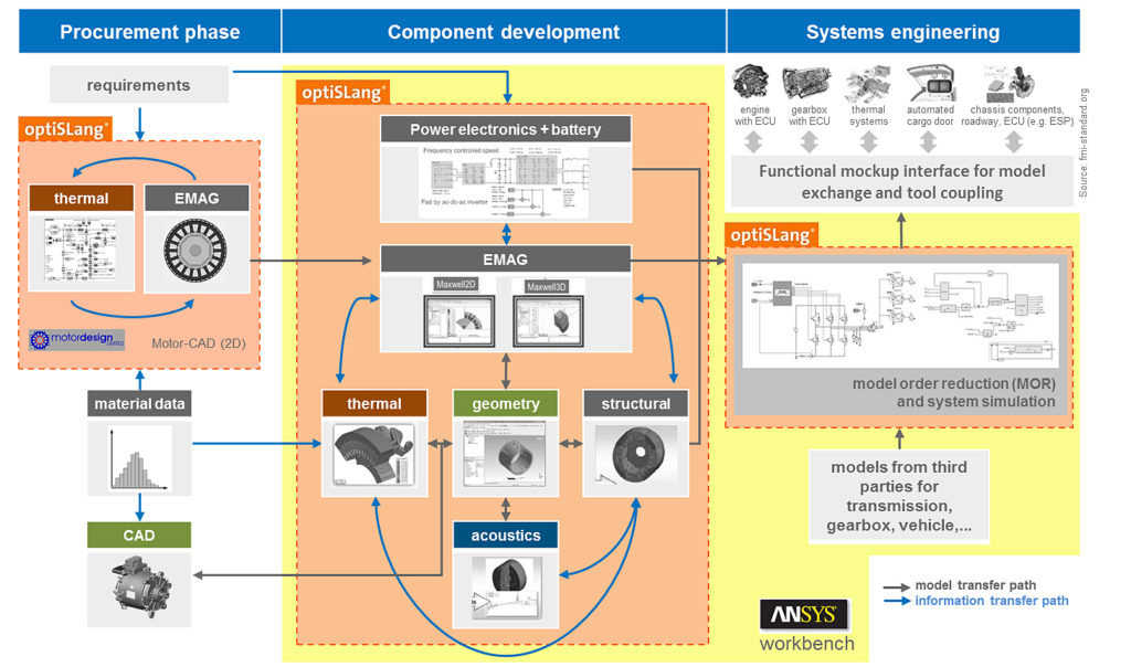 Another advantage of FMUs is that they can be imported into all current software packages for system simulation and can describe, for example, the behavior of the e-machine as a single component in the simulation landscape of a customer or development partner.
Understanding the options
The final challenge is to present the optimized designs so that the customer can clearly understand the different design choices and their trade-offs. EM-motive developed a single radar diagram that transforms all performance indicators into dimensionless variables using the requirements as standardization values.
It includes all domains and their requirements, further highlighted with a colored pie chart in the background, to clearly represent the domains.
All points that are located outside of the 100 percent reference circle meet the design requirements.
Interactions between physical domains are also easily depicted in the diagram. If, for example, a design should be revised to improve acoustics, the mostly negative effects on efficiency are plainly shown.
The chart provides a comprehensive understanding of the strengths and weakness of each redesign and how it fulfills (or doesn’t fulfill) their unique requirements.
Engine design, like many complex processes today, requires a collaborative, systemic approach to be successful.
EM-motive’s systemic approach to engine design integrates the ANSYS parametric simulation environment and an innovative presentation method to ensure that their automotive manufacturing customers can develop the next generation of hybrid and electric vehicles within challenging time and cost constraints.
(Marc Brück, Senior Expert Simulation Technology, EM-motive GmbH, Hildesheim, Germany- This article was originally published on “Ansys Advantage”)


