

Stepper motors play an important role in the manufacturing industry world. Their use prevailigly depends on expectations and applications. If we aim at high precisions, mechanical and electric sturdiness, user friendliness, control and maintenance of the rotor’s position also without power supply, then this motor typology is ideal.
In the present article, we are treating the main typologies of available stepper motors on the market, the essential structural aspects and their operation characteristics in static and dynamic conditions.
The stepper motor is used in small-power drives because it is less efficient than other motors. It allows achieving high positioning precisions and it is suitable for the sectors of robotics, automotive, 2D plotters, 3D printers and several other ambits.
Their name derives from the fact that a well precise angular rotation, precisely called step, is set at each control. They are piloted by opportune electronic switching circuits with open-loop position control. In absence of a specific control, the stepper motor maintains the position reached. In general, we can state that all stepper motors are composed by a stator, where are present the windings made up by copper wire coils, and by a rotor.
In the ambit of the manufacturing industry, stepper motors are classified as follows:
- Permanent magnets (PM);
- Variable reluctance (VR);
- Hybrid (HY).
Permanent magnet stepper motors
The rotor consists of a permanent magnet and shows, on its surface, the same number of poles as those present on the stator, where two phases (or windings) are present.
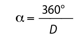
If we indicate with D the number of pole pairs and with α the pole angle, i.e. the angle taken up by a pair of NS (north-south) poles, we can express the following relation:
This type of motor can be excited in three ways:
- Single phase, where windings are powered individually and the rotor rotates at each step by 90° and the entire sequence corresponds to a complete revolution of the same;
- Two-phases, where windings are powered simultaneously, with the rotor that aligns between the two pole expansions (operation used when we want to have high torque);
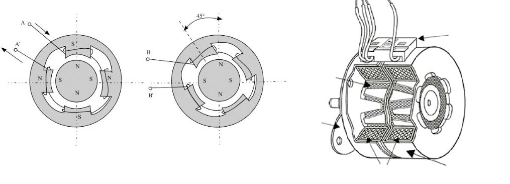
- Half-step. The power supply, in this case, concerns first a phase and then both, successively only the second and so on. At each phase change, the rotation step is by 45°.
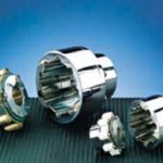
In Figure 1, we can see a schematization of the permanent magnet stepper motor.
Variable reluctance stepper motors
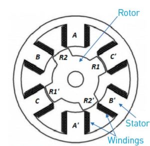
The operation principle of the variable reluctance stepper motor (Figure 2) can be ascribed to the tendency of mobile parts to be arranged in minimum reluctance conditions. This operation corresponds to attaining inductance and maximum flux. Reluctance, precisely, measures the opposition of a material to the transit of the magnetic flux. The VR motor has a grooved-iron rotor and a stator constituted by a stack of laminations with toothed poles. The rotor has a different number of teeth, or pole expansions, from stator’s. The latter features ns teeth, while the rotor body nr=ns±2. The angle among teeth (ϑr/s) is:
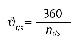
Where s and r stand, respectively, for stator and rotor.
Considering the stator, on each pair of opposite teeth is present a winding that constitutes a phase. The number of phases (F) is given by:
![]()
The minimum number of phases is three (A, B and C). It is not possible to make this motor typology run with two phases only, since the rotation sense would not be determined.
Hybrid stepper motors
The vast majority of stepper motors is hybrid (HY). They group the characteristics of PM and VR motors.
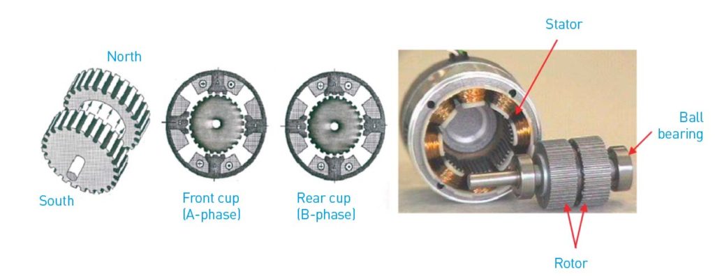
As shown in Figure 3, the rotor is composed by two parts, called cups, magnetized in axial sense (one North and one South), holding a series of teeth alternated to slots. Cups are fitted out of phase, so that the teeth of one correspond to the voids of the other. Indicating with α the angle among the rotor teeth, the phase displacement between the cups is α/2. The stator is similar to the one of VR, with a lamination stack with toothed poles but with just two phases. When the A-phase is excited, the S polarized teeth of the front cup are aligned with the teeth of the N-pole. In the rear cup, with teeth out-of-phase by α/2, the contrary occurs: the N polarized teeth of the rotor are aligned with the teeth of the S-pole of the A-phase. The misalignment between rotor teeth and B-phase ones is worth α/4. When the B-phase is excited, the rotor must rotate by α/4 to be correctly aligned with the poles of the B-phase.
In the successive steps, the front rear cup is always aligned with the N-pole of the excited phase while the rear cup is aligned with the S-pole of the same phase. After Z configurations, the rotor has moved by one tooth, therefore the number of steps per revolution (S) is:
S= nr∙Z
Torque developed in static conditions
Under static conditions, a stepper motor of whatever kind can develop the following torque:
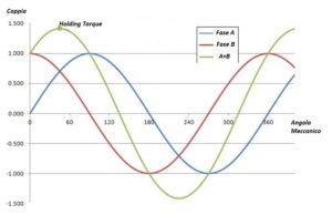
- Holding Torque. Let us consider a stepper motor of any type (PM, VR or HY) and let us power a single phase. The rotor will position itself in a determinate stable position. If, from the outside, we apply a torque and we impose a θ rotation, the magnetic attraction between stator poles and the rotor will oppose the external load, generating an equal opposite torque to the applied torque. Such torque is called holding torque (HT) and it is maximum when the rotation angle of the rotor is equal to α/4, where α is the pole angle, i.e. the angle taken up by a pair of poles. In such condition, rotor’s poles are in intermediate position with regard to the ones of the stator and are subjected to both the attraction of the opposite pole and to the repulsion of the homonymous pole. If we go on increasing the rotation, the stall torque starts diminishing, to the extent of being annulled by an angle equal to α/2. The homonymous poles of rotor and stator are aligned and repulsive forces have null tangential component and create no torque. Such condition corresponds to a situation of unstable balance as the torque is null but a small rotation (positive or negative) is sufficient to make the rotor return to the successive or previous step. The reaction torque, in fact, changes its sign and tends to make the rotor return to the initial position or to the position corresponding to the successive step. The situation illustrated in Figure 4 refers to a PM motor.
- Detent Torque. When a stepper motor is not powered, we would expect a null torque at the rotor. Actually, in PM or HY motors, even in absence of power to the stator phases, a Detent Torque DT appears. The entity of such torque ranges from 5% to 20% of the Holding Torque. In case the motor must maintain the position in absence of power supply, we try to rise the detent torque as much as possible with a suitable profile of teeth. If, instead, such torque is bothering, we will try to minimize it. It is worth noticing that the average value of the detent torque is not null, owing to the friction on bushes.
Torque developed in dynamic conditions
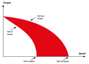
Operating the motor with some piloting circuits, it is possible to assess the operation of stepper motors in dynamic conditions. In technical literature, we can distinguish two operation typologies (Figure 5):
- Operation in pull-out (pull-out torque). The maximum torque the motor can develop during the rotation is called pull-out torque and it is equal to about 90% of the holding torque. In practice, we suggest choosing the size of the motor to work with torque corresponding to about 50% of the Holding Torque. At the so-called pull-out speed, the relative torque annuls. Catalogues, then, provide graphs of the Pull-out torque according to speed.
- Operation in pull-in (pull-in torque). To allow the motor to develop the Pull-out torque, it is necessary that the drive takes it to the wished speed, through opportune acceleration ramps. The frequency of impulses to single phases must gradually increase up to the desired frequency, if we want to develop the pull-out torque. However, drives are not always so sophisticated: in many applications, the still motor is immediately powered at the maximum frequency, without using gradual acceleration ramps. This is the operation in pull-in. If the speed is low, the motor starts in pull-in without difficulty but, at higher speeds than the so-called pull-in speed, the thing is no longer possible and the motor does not start even without load. In catalogues, manufacturers provide the torque curve in pull-in, too.
Conclusions
Stepper motors play an important role in the manufacturing industry world. Their use prevailingly depends on expectations and applications. If we aim at high precisions, mechanical and electric sturdiness, user friendliness, control and maintenance of the rotor’s position also without power supply, then this motor typology is ideal. However, we should take some limits into account, like the impossibility of having high speeds, the heat production and, especially, the need of providing for suitable piloting systems.


