

The Permanent Magnet (PM) motor is a critical part in many electric car powertrain designs, which is undergoing rigorous improvement and changes. PM motors offer compact design and higher system efficiency among other advantages.
The race for the electric cars has begun in the automotive industry and companies are vying for an edge in this market segment. The Permanent Magnet (PM) motor is a critical part in many electric car powertrain designs, which is undergoing rigorous improvement and changes. PM motors offer compact design and higher system efficiency among other advantages.
Electric motor Engineering magazine asked Laboratorio Elettrofisico, a global company that specializes in design and manufacturing of high-quality magnetizing and measurement equipment, to illustrate how to deal with this important process.
In recent years, Laboratorio Elettrofisico (LE) has made great strides in the research, development and implementation of in-situ magnetization for PM rotors in powertrain applications.
MAGNET ARRANGEMENTS
LE offers solutions based on not only the electro-magnetic analysis, but on a complete multi-physics analysis, that includes thermal and stress analysis, pertaining to the in-situ magnetization. Finally, customers are offered custom design solutions, specific to their needs. In most cases, magnetizing systems will typically consist of a dedicated magnetizer along with a custom build magnetizing fixture and associated measurement and automation devices.
The magnetizer is a standalone pulse power supply unit for magnetizing fixtures. It mainly consists of a power capacitor along with its charge and discharge unit. In addition, it contains sophisticated signal processing and other software controllers, managed via HMI-TS display with remote control capability. Beside local remote control, an intercontinental connection is also available for remote service. Tailor made magnetizers feed energy to the magnetizing fixtures, necessary for magnetizing PM devices. Depending upon the electrical conductivity of both magnet materials and surrounding assembly parts, either low capacitance, high voltage configuration or vice versa, high capacitance and low voltage combination may be needed for proper magnetization avoiding eddy current effects. LE latest series of iMag magnetizers caters to all such needs.
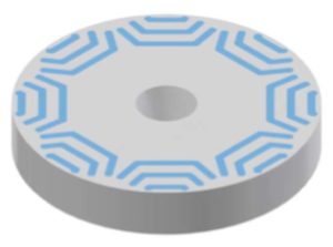
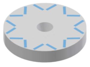
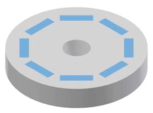
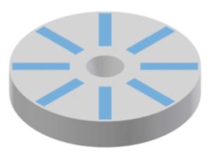
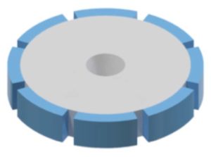
PM rotors come in many different shapes and sizes due to many contributing factors. The magnet position is one such contributing factor. PM rotors can have magnets in V-shape, spoke shaped or they can be surface mounted, among other shapes. Each magnet arrangement necessitates a unique magnetizing fixture with an optimal design besides being durable as well as tailored for mass production.
Magnetizing fixture design is affected by a multitude of factors such as number of poles in the rotor, rotor skew, height of a rotor, magnet material, space availability, customer specific requirements such as particular field along a specified path or surface, etc. Additionally, with growing system complexity, the market requirements are evolving, and, in some cases, customers request to not only saturate the magnets, but also knock them down after magnetization to a desired level of saturation.
Design phase overview
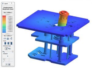
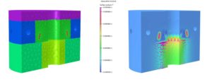
Pulse field magnetization is evaluated using FEA software. Target of this design phase is to simulate the field required for saturating the rotor magnets. Depending on the market needs, field produced on an external surface or path, harmonics, etc. may also be evaluated and used as control parameters. Fixture design starts with electromagnetic FE simulations. Subsequently, thermal behavior and cooling requirements are evaluated, in thermal design phase. Lastly, stress analysis is performed to understand the forces acting on the rotor. These can be exported and provided to the customers if required, to aid in their own mechanical design, or to LE engineering department for the automation design. The above-mentioned design phases are sometimes performed parallelly instead of sequentially to create a feedback loop for complex design cases.
The main tasks of a magnetization bench are to position the magnet correctly during the pulse magnetization process. It also has to withstand large forces generated during the pulse magnetization and the forces generated by the magnets on overall bench post magnetization. These forces can be significantly higher in case of rotor-fixture angular misalignment or if the rotor is not positioned correctly during magnetization. Using electromagnetic FE simulation these forces are evaluated and exported to run a stress analysis on the entire bench, while considering safety factors higher than three or four times Von-Mises stress limit.

Design impact of pole number
For a two-pole rotor a uniform magnetizing field is needed along half the circumference, while on the other hand, for a 30 poles rotor, a sharp magnetization between poles must be obtained. This is successfully done by optimizing the slots design for optimal conductor placement. FEA software and optimization tools are used to adjust parameters such as the slot depth, slot opening etc.
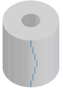
Design impact of rotor skew and height
Typical dimensions of a powertrain rotor height can range up to a few hundreds of mm. Axial distributions of magnets in rotor can be straight, skewed, step skewed. There are two ways to manage magnetization of such long rotors.
- Magnetize the rotor stack by stack with axial steps. This process is usually slow and needs as many numbers of magnetizing shots as the number of stacks in the rotor assembly. This is quite versatile as using the same magnetizing fixture heads, rotors with varying skew patterns and rotor height can be easily magnetized.
- Second method of handling large rotors is to use a single shot magnetization, where the magnetizing fixture is usually taller than the rotor, this process is more energy efficient and only one shot is required, but it is dedicated to one model. If you change the skew angle or the rotor height you would need a different fixture.
Design impact of magnetic material
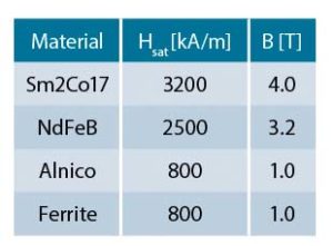
Magnets used in PM motors can be rare earth compounds, such as Nd or SmCo alloys or ferrites or even Alnicos (which are still used in specific cases). Magnet material is the most important deciding factor in the fixture design. It not only decides the energy requirement for magnetization, but also greatly impacts thermal and stress consideration in the design of magnetizing fixtures. For two identical rotors with different magnet material, a particular magnetizer may not be capable of magnetizing both the rotors as the applied saturation field required for each material vary greatly and fixture thermal and safety limits can be constraining factors. In the table 1, the typical values of the saturation field for the most widely used materials are presented.
Positioning of rotors in a magnetizing fixture
Depending upon space requirements and rotor shapes, either an internal or an external magnetizing fixture can be chosen. In an external magnetizing fixture, a rotor has to be inserted and properly oriented, if indexed. In many cases, the fixture itself orients the rotor according to its material anisotropy. Automation may be provided for rapid positioning of rotors in magnetizing fixtures.
Improved winding technology
Winding arrangement can be a key decision during fixture design. Based on each specific requirement, LE may adopt a standard round wire conductor which is an all-purpose solution, or the windings may have skewed slots that follow rotor skewing, to better saturate magnets in each stack. Recently, thanks to the latest 3D printers, LE has started adopting winding guides, which has enabled us to wind the rectangular wires easily in complex designs this greatly improves thermal dissipation and is critical especially when the goal is to reduce the cycle time.
Magnetizing fixture tolerances
One of the most frequently asked questions from LE customers is how strict the positioning tolerances need to be during magnetization. For answering the question and for giving reliable results, LE runs tolerance DOE, whereby small deviations are given to the nominal values and the effect of these deviations on the magnetization are evaluated. In this way, it is easier to decide where to put strict tolerances constraints, and where the constraints need not be strict. This helps automation design team to focus on what really matters for positioning the rotor in the magnetizing fixture.
Measurement
For a reliable system, measurement is indispensable. Some routine measurements include incoming parts mechanical inspection, characterization of the materials and the validation of the results. A typical magnetizing fixture will have measurement systems embedded to check the magnetization process. An embedded flux sense coil detects the flux exerted by the rotor, post magnetization. LE offers diverse measurement solutions to customers for quick and reliable measurement checks such as magnetic imaging systems for post magnetization validation.
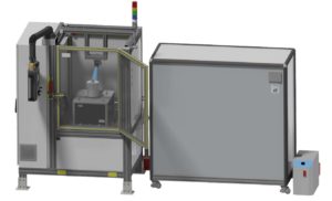
Automation
The magnetizing system is often incorporated with automation system, for rapid rotor positioning, magnetization, measurement and extraction.
An automated process is a good option for fast and repeatable magnetization. Handling big rotors can be troublesome. This required us the design and manufacture of automatic magnetization benches for rapid magnetization and measurement of rotors, integrated seamlessly into a production line. Semi-automatic benches are also offered, where a few operations are manual. For quick inspection, identification cameras, QR readers and reject shooting procedures are implemented.
Only poka-yoke devices with safety as the highest priority are considered in the manufacturing and assembly of magnetizing stations.

