The Synchronous Reluctance Motors (SRMs) are increasingly being used in industrial applications as an alternative to the traditional induction motors and permanent magnet (PM) motors. These motors present many advantages that concern the simple, rugged rotor core, no permanent magnets, no rotor cage and consequently no copper losses which makes it a simple and robust electric motor and can be constructed entirely from high-strength, low-cost materials. The stator is similar to the induction motor one and the rotor presents a transversally laminated anisotropy structure with flux barriers that can be manufactured with normal punching tools at very low cost. The torque depends on saliency ratio which is the ratio of motor d-axis to q-axis inductances.
When compared with PM motors, the Synchronous Reluctance motors are known for their lower specific power and torque, higher noise and lower power factor. Nevertheless, adequate performance can be achieved through accurate sizing procedure.
The design of this type of motor requires a fine analysis for the prediction of machine parameters and performances. That is very difficult because of its highly saturated operating conditions and its salient structure. The use of linear models in evaluating the performances can lead to serious errors since the SRM presents notable non-linear characteristics due to the effects of the saturation and cross-coupling phenomena occurring in the magnetic circuits. These phenomena can be taken into account by an accurate non-linear analysis which can be performed by Finite Element (FE) software.
In this paper, the design and analysis of a Synchronous Reluctance Motor 3 kW, 1500 rpm, 6000 rpm maximum speed, 400 V, for industrial applications is presented. In order to reduce the manufacturing costs, a commercial stator lamination and a commercial housing have been chosen. A prototype with integrated drive has been realized and tested, that combines high-performance drive and motor into a single compact package easy to control.
The design process
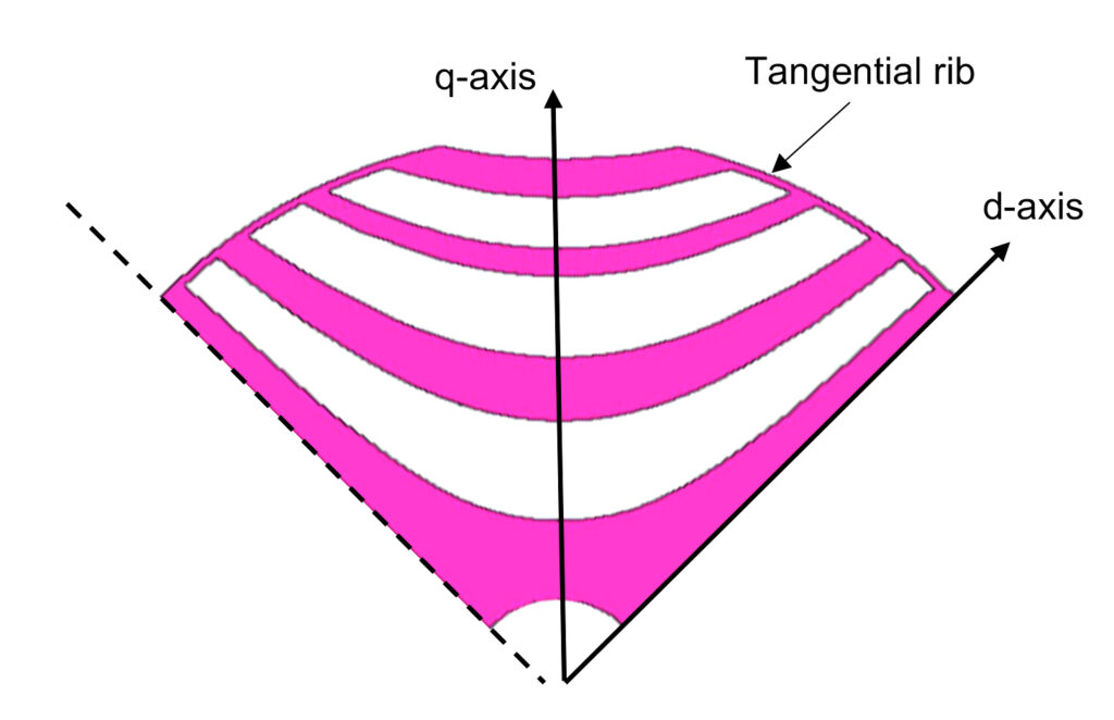
The typical cross section of the rotor is shown in figure 1. The “fluid-shaped” type rotor is preferable because it offers benefits in the increasing of the d‑axis inductance and it has the same behavior in the obstruction of the q‑axis flux of other types of barriers. Some thin connections which are called “rib” connect the ends of the segments to each other in tangential direction. These connections maintain enough mechanical integrity in the rotor structure against rotational forces in high-speed operations.
Since the stator winding of the SRM is sinusoidally distributed, flux harmonics in the air gap contribute only an additional term to the stator leakage inductance. Hence, the equations that describe the behaviour of the synchronous reluctance machine can be derived from the conventional Park’s equations for a wound field synchronous machine.
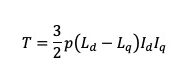
The torque in the rotor reference frame is:
and the power factor is:
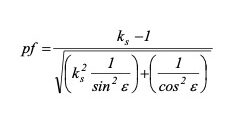
where Ld and Lq are, respectively, the direct and quadrature axis inductances, p is the number of pole pairs, Id and Iq the direct and quadrature axis currents, ks the saliency ratio (Ld/Lq) and e the current angle between the space vector of the stator current and the d-axis current.
The motor is controlled according to the vector control theory and to obtain maximum performance from variable speed drive it is necessary to adopt suitable control strategy. According to consolidated literature, the optimization criteria for the SRM refer to “Maximum Torque per Ampere” strategy.
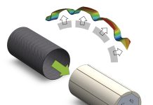
The torque produced by the SRM is due to the anisotropy of the rotor (different d and q axis inductances Ld and Lq) that causes an angular displacement between the space vectors of stator linkage flux and current. In the SRM, both Ld and Lq vary with saturation, and the d-axis inductance is more sensitive to saturation than the q-axis inductance due to the low reluctance path of d-axis flux.
The SRMs exhibit some drawback such as high torque ripple that is mainly due to the discontinuity reluctance change between stator and rotor which can produce vibration and noise. It can be drastically reduced by a fine design of the rotor and stator shape, an accurate selection of the set of rotor barriers and stator slots numbers or by means of the rotor skewing.
The design of these type of motors requires a fine analysis and accurate prediction of machine parameters and performances. For this reason, a design procedure has been carried out using a Finite Element tool in order to take into account the cross magnetization and saturation effects.
Starting from the main motor requirements, the geometric dimensions of the stator and rotor core can be determined by a sizing procedure and then the motor performance are evaluated by FE software. The design of SRM should be aimed to maximize the saliency ratio (Ld/Lq), and the rotor with several flux barriers per pole allows to achieve a high rotor saliency. The thickness of the ribs that mechanically sustain the rotor increases with the rotor speed; this is a significant drawback, since a quite large part of the magnetic flux flows through them, reducing the motor torque.
To this aim the sizing process of the SRM requires accurate optimization procedures with the objective of maximizing the machine performance and reducing the vibration at a given high speed.
A case study
The proposed procedure has been used for the design of 4-pole SRM, for industrial applications; table 1 reports the motor requirements.
| Line voltage | Vrms | 400 |
| Base speed | rpm | 1500 |
| Power @ base speed | kW | 3.0 |
| Torque @ base speed | Nm | 19.1 |
| Efficiency | % | > 88.0 |
| Max speed | rpm | 6000 |
| Power @ max speed | kW | 1.7 |
| Torque @ max speed | Nm | 2.7 |
| Outer stator diameter | mm | 152 |
| Stack length | mm | 170 |
| Shaft diameter | mm | 20 |
| Cooling | Servo-ventilated | |
| Insulation class | H | |
| Type of duty | S1 |
Table 1 – Motor requirements
A commercially lamination has been chosen for the stator core, meaning that only the rotor laminated core needs to be realized, resulting in significant savings in manufacturing costs.
For this design, the lamination with 36 slots and outer/inner diameters of 152×90 mm respectively has been chosen and produced by an Italian manufacturer.
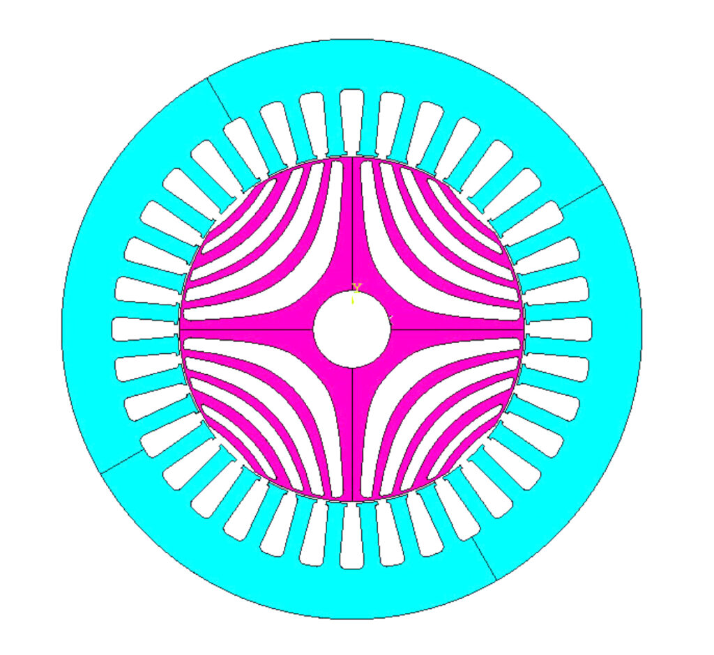
The sizing procedure has allowed to optimize the rotor design only, and figure 2 shows the cross section of the motor and the shape of the flux barriers; the main data are listed in table 2.
The iron bridges (ribs) in the rotor core have been careful sized since they have impact on the motor performance and rotor robustness, and a thickness of 0.50 mm has been fixed in order to guarantee a good mechanical strength of the rotor core at high speeds.
The motor has been analyzed by FE analysis by imposing a “Maximum Torque per Ampere” control strategy and the results are presented in table 3. It includes the motor performance at base and maximum speed: a winding temperature of 100°C has been imposed.
The slot fill factor is 38% and it is compatible with an automatic winding insertion process. The rotor core has been skewed (10 degree) in order to reduce the torque ripple.
| N.pole – N.stator slots | 4 – 36 | |
| N.rotor flux barriers x pole | 4 | |
| Commercial stator lamination: Outer/Inner Diameter | mm | 152×90 |
| Stack length | mm | 170 |
| Shaft diameter | mm | 20 |
| Air-gap length | mm | 0.50 |
| N.turns per phase | 156 | |
| Wire size | mm2 | 1.37 |
| Slot fill factor | 0.38 | |
| Electrical steel | M235-35A | |
| Active materials weight | kg | 18.2 |
| Motor weight (housing included) | kg | 24.0 |
Table 2 – Main data of the optimized design
| Speed | rpm | 1500 | 6000 |
| Phase voltage | Vrms | 204 | 220 |
| Phase current | Arms | 7.82 | 4.24 |
| Torque | Nm | 19.2 | 2.7 |
| Output Power | W | 3016 | 1700 |
| Torque ripple (skewed rotor) | % | 3.5 | 4.4 |
| Joule losses | W | 332 | 98 |
| Iron losses | W | 45 | 54 |
| Frictional losses | W | 10 | 20 |
| Power factor | 0.71 | 0.67 | |
| Efficiency | % | 88.6 | 90.8 |
Table 3 – Motor performance
The motor fully satisfies the requirements; the torque at base speed of 1500 rpm is 19.2 Nm, the output power 3 kW and the efficiency higher than 88%. At maximum speed of 6000 rpm, in the flux-weakening operation, the efficiency is close to 91%. The torque ripple (defined as the ratio between the difference of the maximum and minimum torque values and the average one) is lower than 5%.
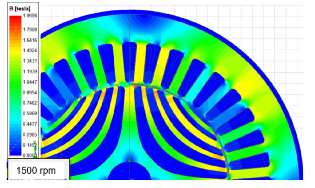
Figure 3 shows the flux density distribution at base speed of 1500 rpm, with maximum values in the teeth and stator yoke below 1.6 T.
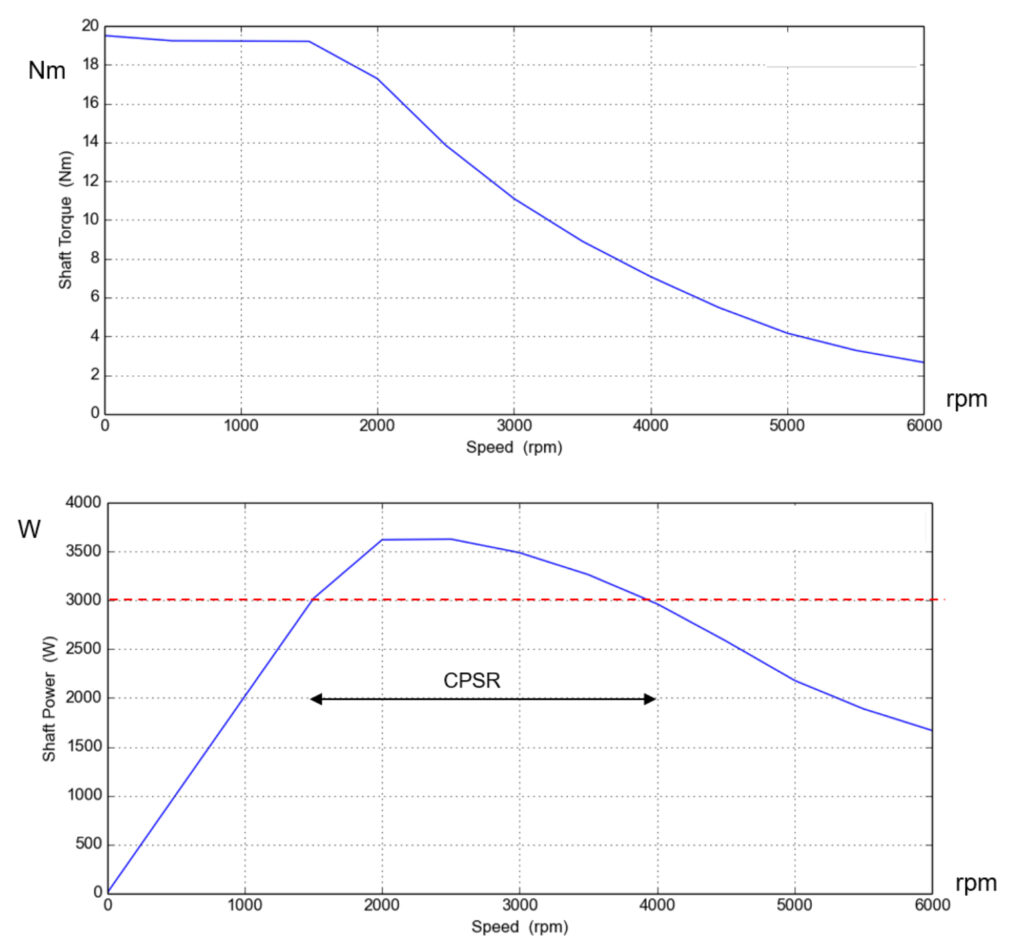
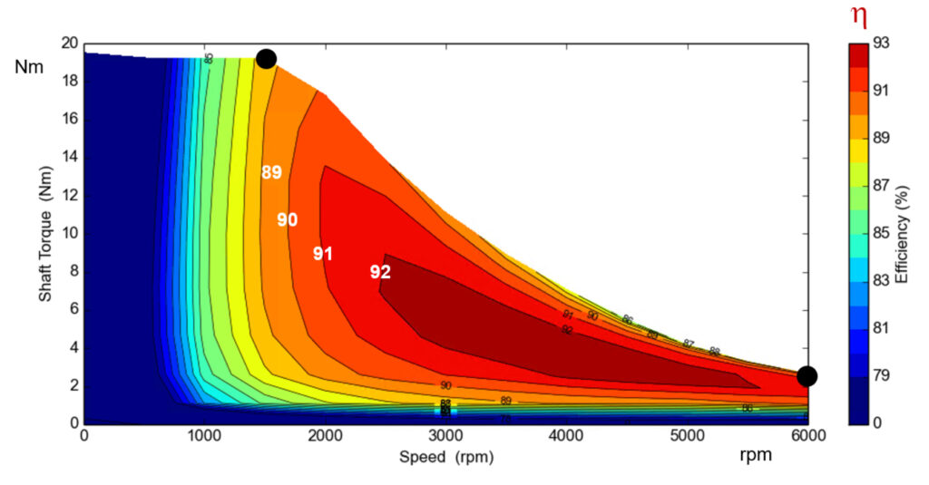
Figure 4 presents the torque and power vs. speed in which it can be seen that the SRM has a wide Constant Power Speed Range (at 3 kW). The efficiency map (figure 5) highlights that efficiency values can even exceed 90% in high-speed operation in the torque range between 2÷10 Nm.
The study has been completed with the thermal analysis of the SRM in order to determine the temperatures in the active materials. The motor is servo-ventilated and a commercial hoising with fins has been chosen.
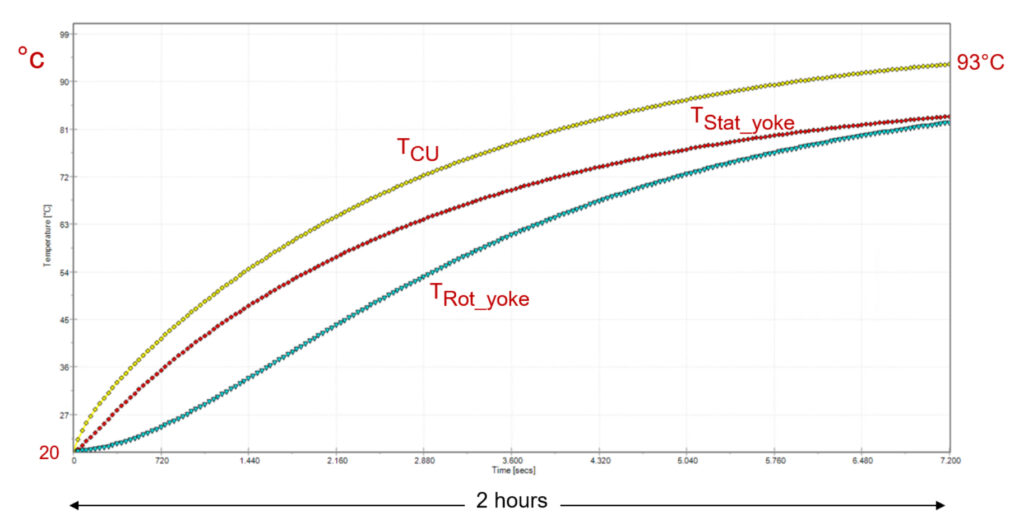
For the thermal analysis, a continuos-duty S1 has been assumed, considering a motor operation of 2 hour, a speed air of 3 m/s and a room temperature of 20°C.
The transient temperature in the winding, stator yoke and rotor yoke are shown in figure 6; after 2 hour the windings reach a peak temperature of about 93°C, below the limit imposed by the H insulation class.
It is important to remark that the motor temperatures strongly depend on the duty-cycle and during the sizing step it is important to check the thermal behaviour of the motor based on the assigned duty-cycle.
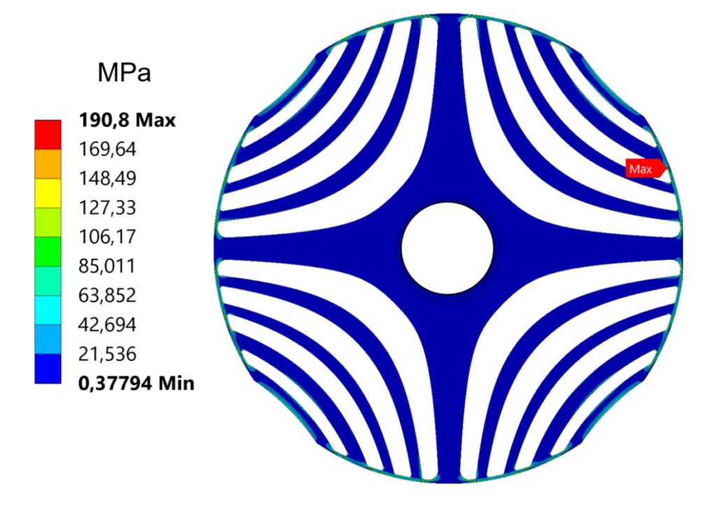
In order to verify the mechanical strength of the motor, an extensive mechanical analysis of the final design has been carried out (figure 7). The mechanical stress due to the centrifugal force at maximum speed (6000 rpm) are below the limits defined, therefore the rotor is suited for high speed applications.
The prototype and experimental tests
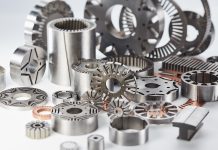
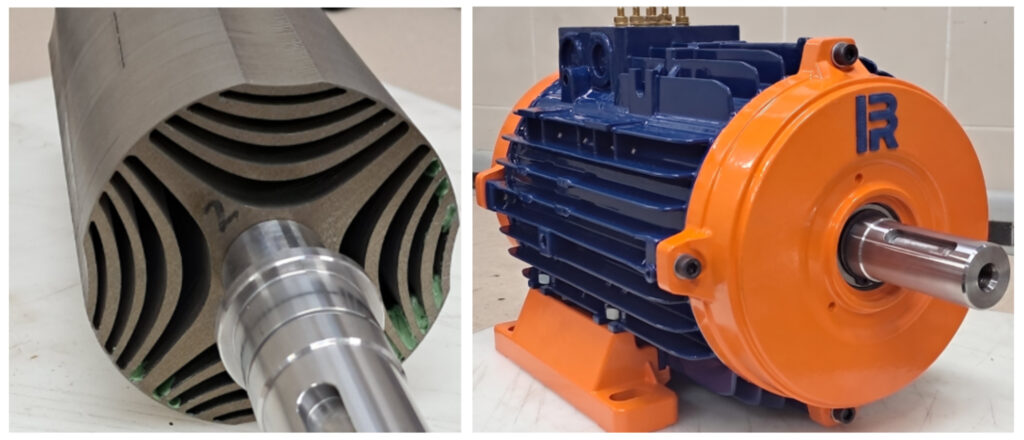
Starting from executive drawings of the optimized design, a prototype has been realized. A commercially lamination has been chosen for the stator and only the rotor cores has been manufactured by laser-cut; a rotor skewing of one slot pitch has been chosen for the reduction of the torque ripple. The electrical steel is the Non-Grain Oriented fully-processed M235-35A (0.35 mm thickness).
A commercially finned housing has been selected, compatible with the stator outer diameter and the motor length (including the end-windings). The stator winding is a single-layer, full-pitch winding, and for the slot insulation the 0.25 mm thickness Nomex have been used. The average phase resistance at room temperature is 1.35 Ohm.
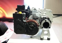
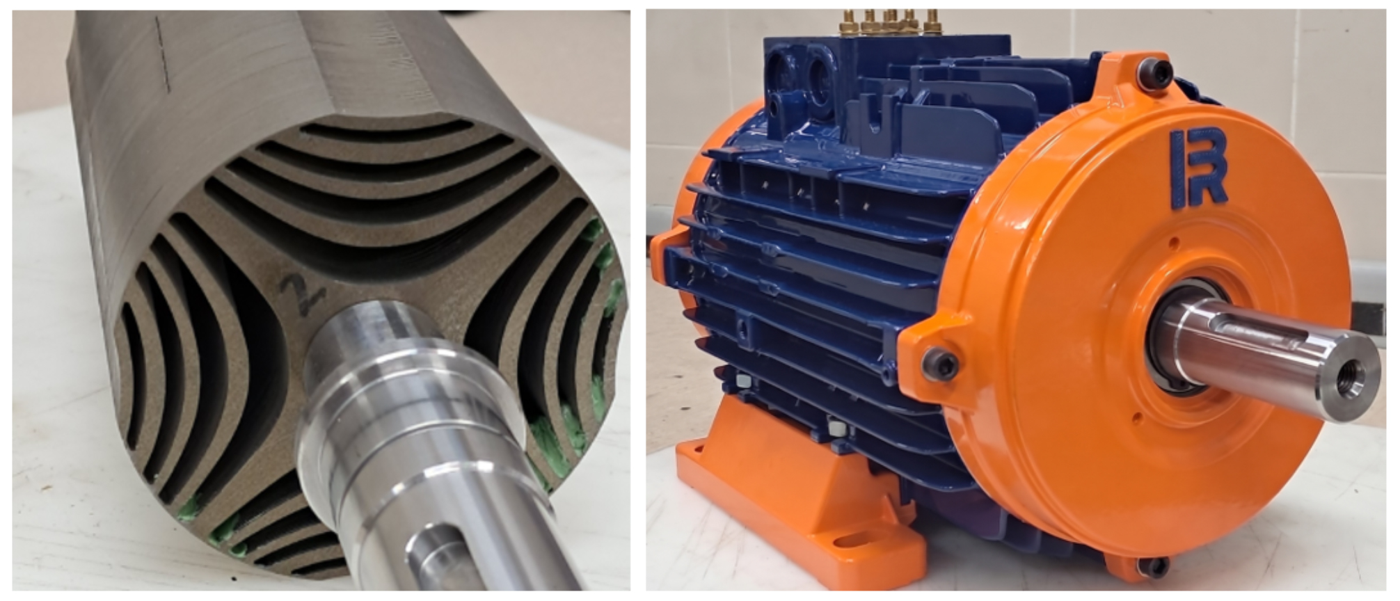
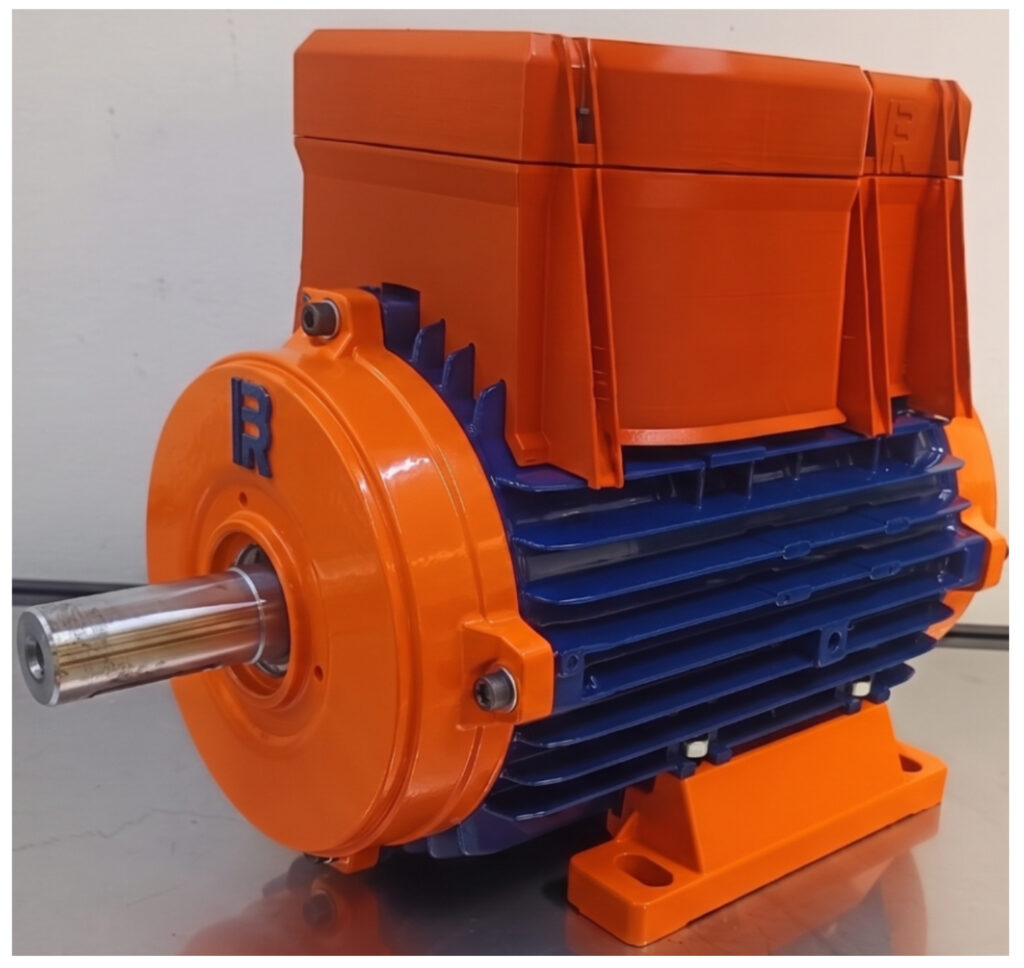
Figure 8 shows the rotor core and the complete manufactured prototype; the drive has been integrated to the motor as shown in figure 9 and represents a compact solution easy to control.
The highly integrated motor-inverter architecture is engineered to optimize space, minimize weight, and enhance overall power density. The system is designed to be directly powered by the 400V AC grid, featuring an internal rectifier stage to internally generate the required DC-link voltage. A robust galvanic isolation barrier is implemented to guarantee absolute operational safety, effectively preventing high-power transients from disrupting sensitive control microelectronics.
At the core of the driver’s efficiency is the implementation of Silicon Carbide (SiC) semiconductor technology. The SiC power stage achieves significantly reduced switching times and minimized switching losses. The inverter operates with an optimized dead-time algorithm, maximizing voltage utilization and output waveform quality. Furthermore, the DC-link stage incorporates high-reliability film capacitors, which deliver superior ripple current handling and exceptional longevity.
Thermal dissipation is efficiently managed via a robust forced-air cooling system combined with specialized top-cooling devices. This topology enables highly efficient planar heat extraction from the top surface of the component packages, significantly reducing PCB-level thermal stress.
The drive has been developed strictly for heavy-duty industrial deployment and each component meets full industrial qualification standards. The assembly is fully certified for shock and vibration compliance, ensuring mechanical and electrical integrity under structural stress.
The SRM motor has been tested through an experimental set-up that includes a digital power wattmeter, torque-meter, load motor, acquisition system and test bench.
The motor performance, at S1 operation, have been evaluated at base speed of 1500 rpm and maximum speed of 6000 rpm. The results are shown in table 4 and point out a good agreement with the FE predictions.
| Speed | rpm | 1500 | 6000 |
| Phase voltage | Vrms | 202 | 220 |
| Phase current | Arms | 8.1 | 4.5 |
| Torque | Nm | 19.2 | 2.7 |
| Output Power | W | 3016 | 1700 |
| Power factor | 0.70 | 0.64 | |
| Efficiency | % | 88.1 | 90.2 |
Table 4 – Experimental results
Conclusions
The Synchronous Reluctance motor presents many advantages such as the simple, rugged rotor core, no permanent magnets, no rotor cage and consequently no copper losses, low material costs and the easy of manufacturing. The design of this type of motor requires a fine analysis and an accurate prediction of machine parameters and performances.
A SRM has been designed for industrial application, as case study, by using a sizing procedure that combined the FE tool with an optimization procedure. Moreover, a commercial lamination has been chosen for the stator core, in order to reduce the manufacturing costs. The motor performances have been presented and also the mechanical characteristics. In addition, the thermal behaviour of the motor has also been tested, at continuos-duty S1, and the winding temperatures are below the limit imposed by the insulation class.
A prototype with integrated drive has been realized that combines high-performance drive and motor into a single, compact package. The drive has been developed strictly for heavy-duty industrial deployment and each component on the board has been selected in accordance with full industrial qualification standards. The motor has been tested and has provided good performance and efficiency levels.
The Synchronous Reluctance motors can therefore be a valid alternative to induction motors and permanent magnet motors in industrial applications and with an accurate motor sizing they can guarantee satisfactory performances at low manufacturing costs.
Acknowledgment: This work was financed by the Regione Abruzzo (Italy) and the European Union under a Research and Development Grant 1.1.1.1.
(by Flavio D’Innocenzo, Gianluca Eleuteri, Federico Visciano, R13Technology; Marco Villani, Universityof L’Aquila, Dept. of Industrial and Information Engineering and Economics)