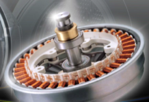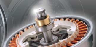
The Synchronous Reluctance motor is a particular type of motor that has neither rare-earth magnets nor the windings inside its rotor core, making it the cheapest solution; as a result, its torque depends only on the rotor anisotropy. The operating performance can be improved by adding a proper quantity of cheaper permanent magnets such as Ferrite into the rotor barriers. Therefore, it can be a good solution for the fractional power applications, and this paper presents the design of a low-cost three-phase, 500 W motor for household appliances. A commercial lamination has been chosen for the stator core, in order to reduce the manufacturing costs.
Introduction
In the household applications, the motor cost is one of the key performance points, in addition to the efficiency and torque requirements. Thus, the synchronous reluctance motors represent a valid alternative in this field, thanks to their lower cost compared with traditional permanent magnet (PM) and induction motors.
Such class of motors present multilayer flux barriers and interesting advantages such as the low inertia, the acceleration performance and the flux weakening operation, but the absence of rare-earth permanent magnets, limits the power factor, torque density, and efficiency level.
The operating performance of the synchronous reluctance motor can be improved by adding a proper quantity of cheaper PMs such as Ferrite into the rotor barriers. The PM-assisted synchronous reluctance motor (PMaSRM) exhibits higher efficiency and power factor compared with pure SRM since the Ferrite not only assists the saturation of the rotor ribs, but also contributes a small amount of torque production
In this paper, the design and analysis of a fractional power PMaSRM is proposed for household appliances, aiming to demonstrate that it is possible to have better performance than conventional induction motors and rare-earth PM motors. Moreover, a commercially lamination has been chosen for the stator core, meaning that only the rotor laminated core needs to be realized, resulting in significant savings in manufacturing costs.
The PM-assisted SRM
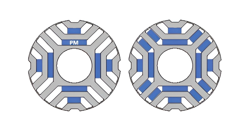
The typical cross-sections of the rotors of PM-assisted synchronous reluctance motor are shown in figure 1. The rotor is characterized by the flux barrier layers and the low-cost PMs are inserted in the middle part of each barrier layer. The amount of Ferrite in the rotor core is limited by the rotor geometry and the manufacturing cost, which is considered one of the design constraints.
The torque of the motor is the sum of both magnetic torque and reluctance torque, as shown in the following equation (in the rotor reference frame):
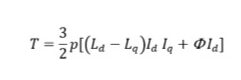
where Ld and Lq are the d and q axis inductances, Id and Iq the axis currents, p the number of pole pairs and F the flux of the PM.
The low-cost permanent magnets, weakening the q-axis stator flux without effecting the d-axis one, increase the angular displacement between the space vectors of stator linkage flux and current. This gives rise a torque improvement of about 20÷30% respect to the reluctance motor without PM and a significant increase on power factor.
The motor is controlled according to the vector control theory and to obtain maximum performance from variable speed drive it is necessary to adopt suitable control strategy.
The design of this type of motor requires a fine analysis and an accurate prediction of machine parameters and performances. That is very difficult because of its highly saturated operating conditions and its salient structure. The use of linear models in evaluating the performances can lead to serious errors since the PMaSRM presents notable non-linear characteristics due to the effects of the saturation and cross-coupling phenomena occurring in the magnetic circuits. These phenomena can be taken into account by an accurate non-linear analysis which can be performed by Finite Element (FE) software.
A case-study
A three-phase fractional power 500 W, 4000 rpm, 4-pole, PM-assisted synchronous reluctance motors has been designed for household appliances. The motor is integrated with the drive fed by 230 Vrms single-phase voltage. This integration gives good benefit and the motor-drive structure combines both the motor and its associated control and drive circuitry within a single enclosure. In order to simplify the manufacturing process, it was decided to select commercial lamination for the stator core; this means that only the rotor laminations need to be realized, resulting in significant costs saving. For this design, the lamination with 36 slots and outer/inner diameters of 90×57 mm respectively has been chosen and produced by an Italian manufacturer.
The main motor requirements and constraints are listed in table 1; the motor is air cooling (natural, no forced air) and the housing encumbrance has been imposed. The commercial FeSi M800-50A electrical steel has been selected, 0.50 mm thickness, and the ferrite Ferrimax 44H (thanks to its easy availability on the market): it has a remanent flux density Br at 20°C of 0.42 T, coercive field strength Hc 300 kA/m, and thermal coefficients for Br and Hc of -0.20 %/°C and 0.50 %/°C respectively.
| Maximum torque | Nm | 1.20 |
| Base speed | rpm | 4000 |
| Power @ Base speed | W | 500 |
| Max speed | rpm | 12000 |
| Housing diameter | mm | ≤ 100 |
| Housing length | mm | ≤ 100 |
| Shaft diameter | mm | 15 |
| Slot fill factor | ≤ 0.40 | |
| Electrical steel | FeSi – M800-50A | |
| Permanent magnet | Ferrite – Ferrimax 44H | |
| Cooling | Air (natural) | |
| Room temperature | °C | 20 |
| Insulation class | F |
Table 1 – Motor requirements
An accurate design process has been carried out to match the required performance while respecting acceptable component costs.
The cross-section of final design is shown in figure 2; the rotor has 2 flux barriers per each pole filled with rectangular blocks of Ferrite magnets. The rotor shape and the PM thickness have been optimized to ensure that the magnets do not suffer from irreversible demagnetization. The iron bridges (ribs) in the rotor core have been careful sized since they have impact on the motor performance and rotor robustness, and a thickness of 0.50 mm has been fixed in order to guarantee a good mechanical strength of the rotor core at high speeds.
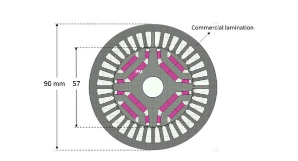
The motor has been analyzed by FE analysis by imposing a “Maximum Torque per Ampere” control strategy and the results are presented in table 2. It includes some of the key dimensions of the optimized design and motor performance. A winding temperature of 110°C has been imposed and 100°C for the Ferrite PM. The slot fill factor is 38% and it is compatible with an automatic winding insertion process.
| N.pole – N.stator slots | 4 – 36 | ||
| N.rotor barriers x pole | 2 | ||
| Commercial stator lamination: Outer/Inner Diameter Slot area | mm mm2 | 90×57 38.6 | |
| Stack length | mm | 50 | |
| Air-gap length | mm | 0.40 | |
| N.turns per phase | 240 | ||
| Slot fill factor | 0.38 | ||
| Phase resistance (110°C) | W | 3.59 | |
| Performances | |||
| Speed | rpm | 4000 | 12000 |
| Torque | Nm | 1.20 | 0.40 |
| Phase current | Arms | 1.95 | 1.48 |
| Current angle | 40° | 71° | |
| Phase voltage | Vrms | 113 | 132 |
| Output Power | W | 500 | 500 |
| Joule losses | W | 41 | 24 |
| Iron losses | W | 22 | 33 |
| Frictional losses | W | 5 | 15 |
| Power factor | 0.86 | 0.97 | |
| Efficiency | % | 88.0 | 87.4 |
Table 2 – Main data e performance of the optimized design
At the base speed of 4000 rpm, the torque is 1.2 Nm and the output power 500 W, with a current slightly lower than 2 Arms, an efficiency of 88% and a power factor of 0.86. At the maximum speed of 12000 rpm, in the flux-weakening operation, the motor exhibits a power of 500 Nm with a current of 1.48 Arms.
Figure 3 shows the efficiency map highlighting the two operating points at base speed and maximum speed. It can be observed that efficiency values can even exceed 89% in high-speed operation in the torque range between 1.0÷0.50 Nm.
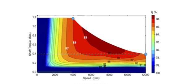
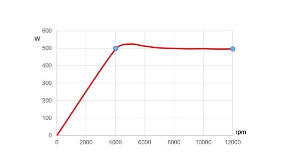
Figure 4 shows the power-speed curve and it can be seen that the power remains constant over a wide speed range (from 4000 to 12000 rpm).
The weights of the active materials, including the housing, are listed in table 3; the weight of Ferrite magnets is 200 gr and the total weight of the motor is approximately 3 kg. In addition, the cost of the active materials has also been estimated (Table 3) and it is slightly more than 12 €, thanks to the significantly cheaper price of Ferrite (10 €/kg) compared with rare earth magnet (70÷80 €/kg).
| Weights and costs | ||
| Stator and rotor core | kg | 1.50 |
| Winding | kg | 0.60 |
| Ferrite PM | kg | 0.20 |
| Active materials weight | kg | 2.30 |
| Total weight (with Housing) | kg | 2.80 |
| Active material costs | ||
| Core (relative to gross weight) | € | 3.2 |
| Winding | € | 7.2 |
| Ferrite PM | € | 2.0 |
| Total cost | € | 12.4 |
| Hp: Electrical steel = 1.0 €/kg; Copper = 12 €/kg; Ferrite = 10 €/kg | ||
Table 3 – Weights and costs
The study has been completed with the thermal analysis of the PMaSRM in order to determine the temperatures in the stator winding and Ferrite. The motor is air cooled and a smooth cylindrical housing, without fins, has been designed. Figure 5 shows an axial view of the motor. The external diameter is 96 mm and the length 85 mm; the motor encumbrance is within the requirements.

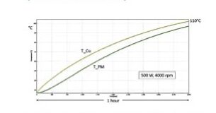
For the thermal analysis, it was assumed that the motor would operate at rated power (500 W) for a duration of 1 hour with a room temperature of 20°C.
The stator winding and PM transient temperatures are shown in figure 6 and after 1 hour the windings reach a peak temperature of 110°C (temperature significantly below the selected insulation class F) and 103°C for the magnets.
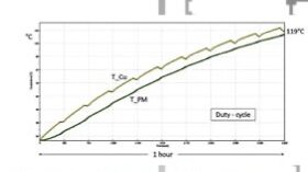
A simple duty-cycle has also been imposed, as shown in figure 7: the operation at the rated power of 500 W for 5 min has been assumed, followed by a high-speed operation at 200 W. This cycle is repeated for 1 hour. Figure 8 shows the transient temperatures in the winding and in the PM; it can be seen that after 1 hour the windings maximum temperature is 119°C and 115°C for the Ferrite.
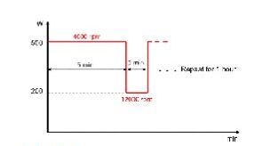
It is important to remark that the temperature depends heavily on the actual duty-cycle of the motor, and during the sizing step it is important to check the thermal behaviour of the motor based on the assigned duty-cycle.
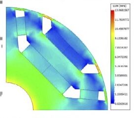
Finally, a mechanical analysis has been carried to verify the mechanical strength of the motors (figure 9). The stresses due to the centrifugal forces at maximum speed of 12000 rpm are below the limit (max Tensile Strength 460 MPa) and no critical issues are highlighted and therefore the designed rotor is suited for high speed operation.
Conclusions
The Synchronous Reluctance motor presents many advantages that concern the simple, rugged rotor core, no rare-earth permanent magnets, no rotor cage and consequently no copper losses. The motor performance can be improved by adding a proper quantity of cheaper PMs such as Ferrite into the rotor barriers.
A fractional power motor has been designed for household appliances, as case study, and a configuration of 4 pole, 36 stator slots and 2 rotor barriers per each pole has been selected as the final design. Moreover, in order to simplify the manufacturing process, a commercial lamination for the stator core has been chosen.
The motor performances have been presented and also the mechanical characteristics. The results are satisfactory and the motor exhibits good efficiency and power factor values and a wide constant power speed range. In addition, the thermal behaviour of the motor has also been tested, and the winding temperatures are below the limit imposed by the insulation class. A mechanical analysis has also been performed to verify the mechanical strength of the rotor at maximum speed.
The estimated cost of active materials is slightly more than 12 €, thanks to the significantly cheaper price of ferrite compared with rare-earth magnet. The PM-assisted synchronous reluctance motor could be a valid candidate for use in household appliances due to its lower cost compared to induction motors and PM motors and through a careful design it can guarantee good performance and efficiency levels.