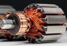
For the designer, the white sheet is filled starting from the rotor volume, sized through the famous Esson equation. This relationship tells us that the active volume of the machine (D2L) is the physical result of the effort required:
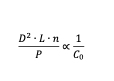
In simple terms, the sizes of the rotating “cylinder” (diameter squared by its length) depend on how much you strain the material. Here the designer finds himself at the first crossroads: increasing the current density would allow implementing very small motors, but it would generate an unmanageable heat for common insulants; pushing too hard on the magnetic flux, instead, would saturate the iron, degrading the efficiency of the motor itself. The art resides in positioning ourselves in the middle, typically working with air gap inductions around 0.7-0.9 Tesla, to guarantee a good power factor without overheating the machine. Once defined the volume, it is necessary to shape the inner geometry according to the speed requested, that is to say the number of poles. Given the same nominal power, a golden rule applies: sizes are dictated by the torque. A 2-pole motor (high speed, around 3000 rpm) delivers low torque, permitting the use of a compact casing. On the contrary, an 8-pole motor (low speed, about 750 rpm) must generate four-times the torque: to support this electromagnetic effort, the designer is compelled to increase the active volume, adopting a remarkably bigger and heavier casing.
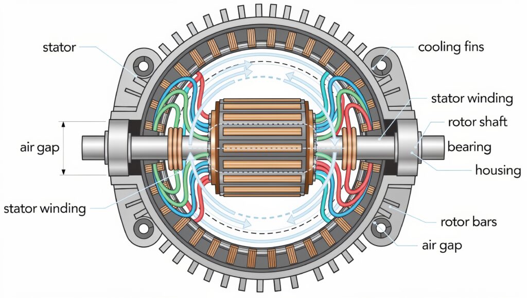
The air gap, a thin layer of air between stator and rotor, is the most critical part of the entire design. It must be infinitesimal (often few tenths of millimetre) to minimize the necessary current to magnetize the circuit, but large enough to avoid catastrophic contacts in case of thermal expansions or wear of bearings. Precisely here the mechanical precision becomes a fundamental electrical parameter. Finally, the iron must be “dressed” with copper. The number of turns per phase is calculated to balance the mains voltage according to the fundamental law of electrical machines:
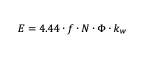
Where frequency (f), flux (Ф) and turns (N) must be harmonized with the winding factor (kw), a parameter that reminds us that turns are not concentrated in a spot, but distributed in slots. Besides, precisely slots represent the last geometrical challenge: designing a stator tooth large enough to prevent the saturation with the magnetic flux, but leaving a slot large enough to host the necessary copper. It is a millimetric struggle, trying inserting as much copper as possible into a narrow space, knowing that the residual air is the worst enemy of the thermal dissipation.
From theory to practice
If the electromagnetic sizing represents the soul of the motor, materials and manufacturing technologies constitute its skeleton and muscles. A theoretically excellent design can turn into a commercial failure if not supported by appropriate construction choices. The first critical element is the choice of the magnetic material. For stator and rotor, we do not use common iron, but NOES – Non-Oriented Electrical Steels. The silicon presence increases the electrical resistivity of the material, hindering the circulation of eddy currents, which represent one of the main sources of energy losses and of heating. Here, the manufacturing technology plays a fundamental role. The magnetic core is made by superimposing thin sheets of metal, insulated from each other by an organic or inorganic coating of few microns. Reducing the thickness from 0.50 mm (standard) to 0.35 mm or even to 0.20 mm drastically decreases iron losses, enabling the motor to reach higher efficiency classes (IE3, IE4). However, thinner sheets of metal are more expensive and hardly handled during the production process. During blanking, the mechanical action of the die alters the crystalline structure at the edge of the sheet metal, degrading its magnetic properties. This phenomenon is mitigated through an attentive control of the die wear and, in some cases, by means of thermal treatments. Once blanked, metal sheets are successively packaged.
The presence of porosities or blowholes inside the bars or the short-circuit rings alters the local electrical resistance, creating current imbalances that generate vibrations and localized thermal “hot-spots”. For this reason, the process quality is fundamental. For Super Premium Efficiency motors, the technology is gradually shifting to copper. Since copper has an approximately 60%-higher electrical conductivity than aluminium, losses drastically drop. Nevertheless, the melting point of copper (1085 °C against 660 °C of aluminium) makes the die-casting process extremely complex for the life of dies.
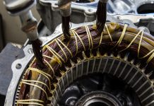
Once assembled the stator pack, we enter the delicate world of insulants and windings. Copper conductors are coated by polymer enamels able to withstand high temperatures and strong voltage gradients. In the modern era, where the use of inverters (VFD) is omnipresent, the insulating system must withstand not only temperature, but also voltage spikes generated by the electronic switching, which can cause partial discharges among turns. For this reason, Grade 2 or 3 wires are used (double or triple enamel layer), as well as composite slot insulants. The process culminates with the impregnation, phase that transforms a whole of vibrating wires into a solid monolith. The reference technique for high-quality motors, and mandatory for many ATEX executions, is the VPI (Vacuum Pressure Impregnation).
The process occurs in autoclave: first, a high vacuum is applied to extract every trace of air and moisture from the porosities of windings; afterwards, the resin is introduced and a strong pressure is applied to force its penetration into every interstice. The result is a winding free from air voids. This is crucial for three reasons: eliminating air prevents the triggering of corona discharges; the resin conducts heat much better than the stagnant air, facilitating the thermal transfer; the cemented winding does not vibrate under the effect of electromagnetic forces, preventing the enamel abrasion.
Energy efficiency and IEC regulatory framework
If until some decades ago the efficiency of an electric motor was considered one technical feature among many, today it is the dominating parameter that drives the whole product development process. The boost is not only ethical or economic, but legislative. The benchmark for the operators in this sector is the IEC 60034-30-1 regulation, which classifies three-phase squirrel-cage asynchronous motors (mains powered) according to their efficiency. The standard defines the classes that are nowadays known to all players:
- IE1 (Standard Efficiency): currently technologically surpassed and banned from the European market for the vast majority of applications.
- IE2 (High Efficiency): the base level for some powers or for motors piloted by inverter.
- IE3 (Premium Efficiency): the current mandatory reference standard in EU for power ranges from 0.75 kW to 1000 kW.
- IE4 (Super Premium Efficiency): the new target for high energy-saving applications.
- IE5 (Ultra Premium Efficiency): the technological frontier, often reachable only with hybrid or reluctance technologies, however pursued by the pure asynchronous, too.
In physical terms, changing class means acting surgically on the five loss categories that constitute the energy balance of the machine:
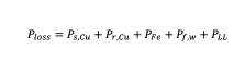
Where losses are respectively: stator Joule, rotor Joule, Iron, Friction /Ventilation and the insidious additional losses. Joule stator losses often constitute the biggest slice of the cake. To reduce them, the designer can increase the quantity of active copper. This implies the use of either deeper or larger slots which however subtracts space to the iron, risking of saturating the magnetic circuit. We are often compelled to increase the length of the sheet metal pack to host more conductive
material, which impacts on costs and on the axial overall dimensions of the machine. Joule rotor losses are directly proportional to sliding. A more efficient motor is intrinsically a motor that turns at a speed closer to the synchronism one. To obtain this result, we must increase the section of rotor bars or improve their conductivity. However, reducing the rotor resistance too much reduces the starting torque.
Additional Losses under Load arise from field harmonics, leakage fluxes in heads and transverse currents among imperfectly insulated metal sheets. To knock them down, we must work at the geometry. The aerodynamic profile of the blades and fins of the casing is designed to ensure the heat dissipation with minimal air resistance. In some IE4 motors, the fan diameter is decreased accepting a slightly higher work temperature (however, always within the F or B class), just to gain that tenth of a percentage point of efficiency.
Finally, there is the tolerance aspect. The IEC 60034-1 regulation allows tolerances on the guaranteed values (for instance, 15% on total losses for powers > 150kW). However, we cannot rely on the tolerance to declare an efficiency class. If a motor is designed at the boundary between IE2 and IE3, the variability of the mass production (ex. a batch of slightly worse magnetic metal sheet or an imperfect die casting) risks of making the product uncompliant with the specification. For this reason, the sturdy design always provides for a safety margin on theoretical calculations, always ensuring the conformity with plate data.
The safety challenge: designing in ATEX ambit
If the energy efficiency is a matter of economy and sustainability, the ATEX (Atmosphères Explosibles) design is a separate issue. When an electric motor is installed in a petrochemical plant, in a mine or a grain storage silo, it ceases being a simple actuator and becomes a potential source of ignition in an environment saturated with gases, vapours or combustible powders. Here, the margin of error is zero: a single spark or a hot spot on the casing can trigger a catastrophic chain reaction. The legislative reference that rules this world in Europe is the 2014/34/UE Directive, which imposes essential safety requisites for appliances intended for uses in potentially explosive atmosphere. In the engineering practice, the most fascinating and complex challenges are surveyed in the design of motors for Zone 1 (high danger probability), where construction philosophies fork into two main paths: the explosion containment (Ex db, explosion-proof casings) and the ignition prevention (Ex eb, increased safety).
The design of an Ex db motor (Flameproof) is an exercise of mechanical sturdiness. The principle is not preventing the gas from entering the motor (event deemed impossible), but managing the possible internal explosion. If the explosive mixture penetrates and triggers inside the motor, the casing must withstand the overpressure generated (which can exceed 10-15 bars of instantaneous peak) without deforming or breaking. However, the real secret resides in flame paths. The coupled parts of the motor are not hermetically sealed, but designed to the hundredth of a millimetre according to the specific gas (IIA, IIB or IIC group). When the combustion gases from the internal explosion try escaping through these gaps, they are forced into a long narrow path. The contact with the large metal surfaces removes heat from the pressure wave, cooling it under the ignition temperature of the external mixture.
The Ex eb (Increased Safety) philosophy is completely different. Here the goal is preventing the arc flash or the excessive temperature. It is not acceptable that the motor can spark internally. This imposes strict electrical constraints: the rotor cannot, by definition, spark (therefore, only squirrel cage, no collectors), and stator connections must be oversized and locked to prevent loosening. The critical parameter for the Ex e is the necessary time so that, in locked rotor conditions and starting from the steady-state temperature, windings or rotor reach the limit safety temperature. The designer must ensure that thermal protection devices (motor protection relays) intervene in a shorter time. This often compels to reduce the design current density, resulting in physically larger motors than their standard counterparts, precisely to slow down the thermal dynamics in the event of a fault.
Irrespective of the protection method, the “invisible enemy” remains the surface temperature. Every gas or powder has a self-ignition temperature. The motor is classified in Temperature Classes, from T1 (450 °C) to T6 (85 °C). Designing a T3 motor (200 °C) is relatively simple for a standard industrial machine. However, designing either a T5 or T6 motor (for instance required in presence of Carbon Disulfide) is an extreme challenge. It means that, in the worst case (overload, maximum environmental temperature, dust layer on the casing), no external part of the motor must exceed 85 °C or 100 °C. This needs an exceptional ventilation system, low-loss magnetic circuits and an active monitoring by means of thermal probes (PTC or PT100) embedded in windings, which become integral part of the safety certification.
We should not forget electrostatics. In ATEX environments, even a standard plastic cooling fan can become lethal if it builds up an electrostatic charge and suddenly discharges it. For this reason, conductive plastic fans (charged with graphite) or metal ones (aluminium, brass) are used, but with one precaution: if the fan is made of metal and breaks or comes off, the impact with the fan cover must not generate mechanical sparks. Often, increased safety distances or coupled materials that do not produce hot sparks are required (for instance, brass on steel).
Testing and validation
Testing is not a mere bureaucratic formality, but a severe process codified by the IEC 60034-1 regulation, which clearly distinguishes between Routine Tests and Type Tests. Routine tests are non-destructive tests, essential to guarantee manufacturing quality and safety of every motor. They include measuring the resistance of windings (to check there are not short-circuited turns or errors in the number of turns), the measurement of the insulation resistance and the dielectric strength test.
Much more complex are Type Tests, executed on the first prototype or on a statistical sample to validate the whole design. The queen of these tests is the Heat Run Test. The motor is coupled to a dynamometer brake and brought to the nominal load. We let the machine run until the temperature stabilizes. At this stage, the temperature of windings is measured. The most accurate method, required for certifications, is not the use of thermocouples (which measure only one point), but the change in resistance. Exploiting the physics of copper, whose resistivity clearly increases with temperature, the average temperature of the winding is calculated. At the same time, we proceed to the efficiency determination according to the IEC 60034-2-1. As mentioned in the efficiency section, using the Loss Segregation Method, the motor is tested under various conditions: no-load (to separate iron and mechanical losses), locked-rotor (for Joule losses) and with partial load (25%, 50%, 75%, 100%, 115%).
Conclusion
Although the three-phase asynchronous motor technology is mature, it is not stagnant at all. The leading trend is the native digitalization. High-end motors are no longer silent, but they are conceived with integrated sensors (IoT) that monitor vibrations, bearing temperature and stray magnetic flux. These data are sent to the cloud, thus enabling the predictive maintenance, warning the operator weeks before a bearing fails or the insulant degrades, transforming the motor from passive component to a smart factory node. From the electromagnetic point of view, the challenge to rare earths is urging towards the return and evolution of alternative technologies. SynRM (Synchronous Reluctance) motors, or their variant assisted by ferrite magnets, are gaining market shares. These machines eliminate rotor losses (since the rotor has neither cage nor induced currents, but it is just iron shaped to guide the flux), permitting to reach IE5 efficiencies with lower costs and overall dimensions than the asynchronous, although they mandatorily need an inverter to work.
In short, the design of electric motors remains an art in evolution. The matter is no longer converting electric energy into mechanical, but to succeed in it with the highest possible efficiency, ensuring absolute safety in explosive environments and getting integrated in complex data networks. For the product engineer, this means that competence can no longer be vertical: electromagnetism, thermodynamics, science of materials, ATEX regulations and power electronics are nowadays indissoluble chapters of the same design manual.