Drives constitute an essential part of the manufacturing sector because they are the real “muscles” of CNC machines. in this article the main typologies available on the market are analysed.
The drive is a suitable system for performing a linear or rotary motion and includes both the motor and its control system. It is possible to classify them according to the three main application fields:
- Drives for the spindle rotation;
- Drives for x,y, z linear axes;
- Drives for circular axes
Historically, concerning the spindle, they used systems with motion transfer to belt and gears: the latter allowed achieving a transmission whereas the belt reduced vibrations. Such system assured high power and torque values but low speed values. The motion transmission could occur also through a coupling: this represented a “safety” aspect for the machine tool because, in case of anomalies, it broke down without damaging the machine. In comparison with the first case analysed, the motion transmission through coupling assured higher speeds to the detriment of powers. Precisely the electrospindle has allowed finding the right compromise in terms of speed and power (that is to say, integrated motor and spindle). This has also enabled to obtain more compactness and lower vibrations.
Motors integrated into the spindle
Until 2000, DC motors were used but with the advent of technology and a substantial improvement of power electronics (more and more powerful microprocessors and development of inverters), it was possible to introduce AC ones. Direct current motors allow a precise regulation of torque and nominal power. However, they are scarcely sturdy and rather expensive, besides needing a quite ordinary maintenance of the collector and of brushes. Moreover, they are cumbersome motors (in general, speed increases hand in hand with sizes). As time went by, alternating current motors were developed. The have discretely adjustable speed through a speed gear but they also strongly depend on frequency, as indicated in the following formula:
n = 60 * f/p
where:
n= rotation speed (rpm)
f= net frequency
p=number of polar torque
A noteworthy novelty was the introduction of the inverter that, in alternating current motors, has allowed varying the net frequency, permitting to increase the variability range of the motor speed. AC motors are very reliable, simple and highly performing. In CNC machines is broadly used the so-called electrospindle, a very compact and stiff system, which allows achieving high torque and speed.

Motor of linear axes
To move the linear axes of the machine tool, rotary motors are almost always used and therefore it is necessary to combine a system that transforms motion from rotary to translating. The motion transformation system is composed by a system with re-circulating ball screw in case of CNC machines and by a screw-nut screw system in case of a conventional machine. In general, the characteristics demanded to a motor for linear axes are the following, as listed below:
- Each axis must be equipped with an independent drive;
- Motors must be compact;
- They must permit progressive speed variations;
- They must have very high rapid feed speeds to reduce transients as much as possible;
- High pickup and braking currents;
- High accelerations.
Among the solutions most adopted, it is worth highlighting:
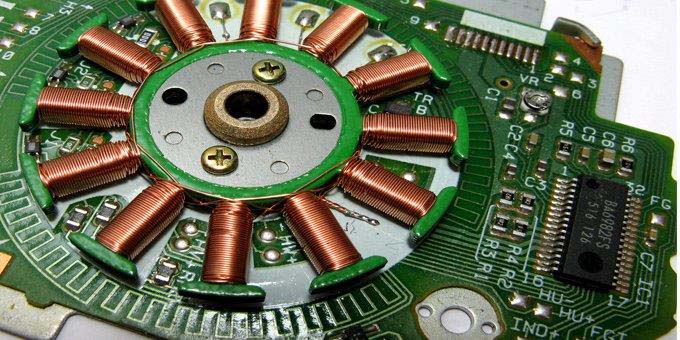
- DC servomotor with permanent magnets. Generally, the DC motor that powers the spindle is equipped with windings on both the stator and on the rotor and therefore they are independent excitation motors. In the motor for linear axes, the windings on the stator are instead replaced with permanent magnets. Windings are mounted on the rotor and they receive electric current from brushes. The latter, however, are subjected to wear and, for that reason, they need periodic maintenance. To avoid that, “brushless” servomotors are used, in other words without brushes and with magnet on the rotor and winding on the stator part. In this way, motors become even more compact but the problem of the rotary magnetic field management emerges. Therefore, powering the winding on the stator in controlled manner becomes necessary, in order to minimize torque and speed oscillations. Hall-effect sensors are used, as they can manage the switchover of the winding on the stator as they detect the magnetic field generated by the rotor and its relative position as to the rotor. Concerning the switchover, it generates some torque instabilities called, precisely, torque ripples. The main advantages of a brushless motor, in comparison with a standard DC motor with permanent magnets, are the following:
- Higher rotation speed;
- Low inertias;
- Inferior nominal torque to the DC one but with a maintenance of the torque itself for a much longer time;
- Higher efficiencies;
- Smaller overall dimensions;
- Low maintenance.
2. Stepper motor. It is a synchronous motor where the rotation speed is varied by changing the frequency of control pulses. The operation is very simple: whenever the motor detects a pulse, it rotates by a certain angle. The torque in this case is not constant but it rapidly decreases as the speed rises. It is a very precise motor and therefore it grants certain result sureness. Sizes are very small.

Motors for rotary tables
Recently, they have developed linear motors that allow solving the problem of the motion transformation from rotary to linear, because approximate 15% losses occurred with the motor transformation. The linear motor is a real “linearization” of the brushless motor. It is worth noticing that the motor is as long as the axis to be driven. Therefore, magnets must be perfectly aligned. Then, we refer to:
- Long inductor, when magnets are positioned on the fixed part;
- Short inductor, when magnets are positioned on the mobile part.
- Among the advantages, we are pointing out:
- High speeds;
- High accelerations;
- High precisions;
- High stiffness.
Nevertheless, they are affected by some relevant limits, like:
- Low efficiencies;
- A bit complex heat disposal;
- High costs;
- Redesign of the machine tool.


