

Fault-tolerant modular electric drives represent an already feasible solution to assure the reliability requisites of aeronautical applications. Prototypal studies and systems already operating in aircrafts confirm it. To understand better the characteristics and the specificities in this applicative ambit, we have talked about that with Professor Marco Tursini, ordinary professor of the Department of Industrial and Information Engineering and Economics at L’Aquila University.
Fault-tolerant electric drives arouse lively interest in aeronautical applications because they allow satisfying their strict reliability specifications. A modular design permits to obtain electric motors with high power density and high efficiency, as well as intrinsically fault-tolerant, without turning to the complete redundancy of the actuator.
Extending the approach to power electronics and to control, the use of electrical drives can be hypothesised not only in service motions but also in “safety critical” functions of aircrafts, such as primary flight controls.
To understand better the characteristics of multi-phase fault-tolerant drives in this operational ambit, the state-of- the-art and the new opportunities, we faced the issue with Professor Marco Tursini, ordinary professor of the Department of Industrial and Information Engineering and Economics at L’Aquila University, who reported as example some projects developed by his research team.
The added-value of modularity
In recent years we witness the growing use of electric drives in aircrafts, trend indicated by the English acronym MEA (More Electric Aircraft). The basic idea is replacing the conventional hydraulic and pneumatic actuation systems with more compact and lighter electric systems, to reduce consumptions and fuel costs, to allow longer flight routes and to decrease emissions.
The electric drives commonly used in industry cannot satisfy the reliability requisites demanded in aeronautics, especially in those functions on which depends the safety itself of the flight and of passengers.
These limits, connected with both the structure of motors and control electronics, have led researchers to explore new system architectures, able to guarantee the demanded reliability without turning to the complete redundancy, i.e. maintaining compactness and lightness features. «A possible solution – explains Professor Marco Tursini, Department of Industrial and Information Engineering and Economics at L’Aquila University – consists in considering the redundancy in terms of “phases” of the electric motor, directly in the design activity.
Such concept leads to the development of multiphase modular drives, able to satisfy the basic principles of the fault-tolerance of an electromechanical actuator, in other words the electric, magnetic and thermal insulation among phases».
We are hereunder illustrating some solutions developed on such principles by the research team of L’ Aquila University, coordinated by Professor Tursini, in the ambit of funded projects concerning the drive of flaps, of a cart lift system and of the tail rotor of a helicopter.
Examples of specific applications
The “flap actuator” (FA) is designed to move the flaps positioned on the trailing edge of aircrafts’ wings. Flaps are generally used just for some seconds during landing and take-offoperations and are “safety critical” systems of the aircraft because their failure affects the flight mission.

The CLS, Cart Lift System is instead a service lift used for the transport of foods and drinks between the hold and the passenger cabin in large aircrafts. Its failure affects passengers’ comfort and serenity and the same reliability specifications as for flaps are required. Both FA and CLS systems are based on a re-circulating ball screw device that translates the rotary motion to linear, whose mechanical view is illustrated in Figure 1.
The ETRD (Electrical Tail Rotor Drive) project, developed in the ambit of the European “Clean Sky” research programme, concerns instead helicopters with tail rotor drives of “Fenestron®” type, fully integrated into the terminal part of the tail beam, such as H 160 of Airbus Helicopters.
«In this case–Prof. Tursini underlines– the project target is the replacement of the current mechanical architecture, where the motion is taken by the main rotor and transmitted to the tail, with an electric motor directly coupled to the blades of the tail rotor, with the advantage, in addition to the system simplification, of guaranteeing a total decoupling between the speeds of the turbo-shaft engine and of the tail rotor, so notably widening the aircraft’s manoeuvre capability».
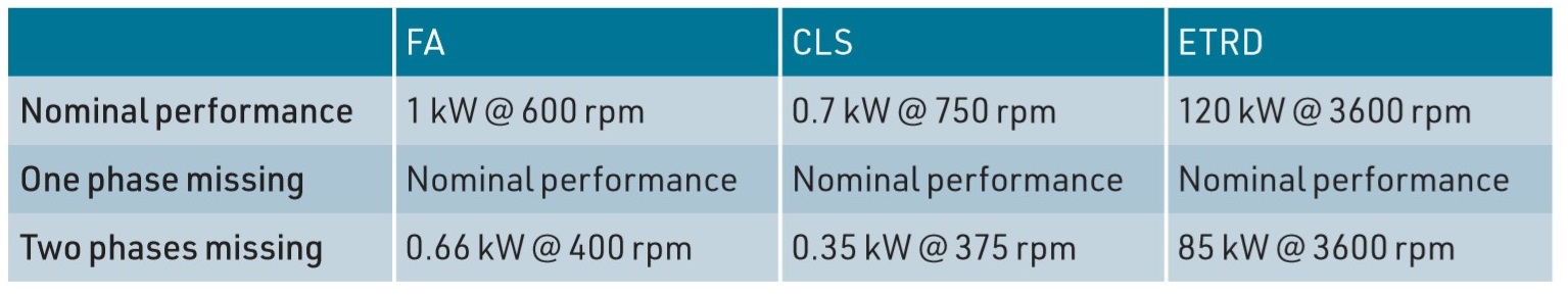
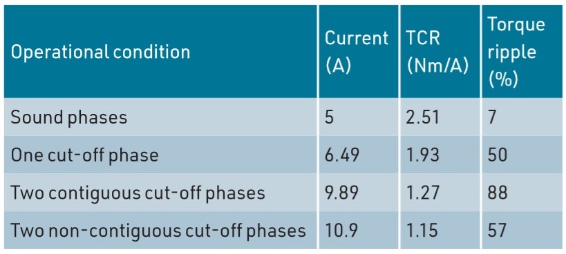
Fault-tolerance specifications impose that the loss of one phase owing to failure does not affect the capability of delivering the nominal power of the actuator, whereas with a further second loss it is possible to supply reduced power, decreasing torque or speed depending on applications, as we can deduce from Table 1.
The fault-tolerant motor
The modular approach of fault-tolerant drives finds its natural implementation in switched reluctance or permanent magnet motors of “brushless DC” type (PM-BLDC).
The structure of the latter, preferred due to the higher achievable power densities, is illustrated in Figure 3.
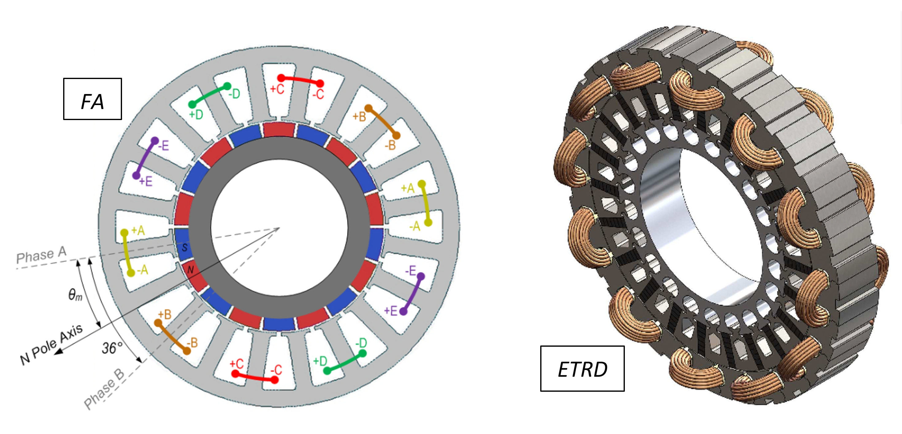
«The electric independence –Professor Tursini highlights– is first of all implemented by powering the phases separately. Phase windings are made with coils arranged on protruding poles and by alternating wound and unwound poles. This implementation favours the failure reduction, through both the physical separation among the coils of the different phases and through the minimal overlap among the respective wirings. The arrangement on alternate poles features a low reciprocal inductance among phases, guaranteeing a substantial magnetic independence and a minimal thermal interaction. These engineering solutions allow avoiding the failure in one phase affects the others».
For the flap application, they have adopted the solution with five-phase PMBLDC motor, internal rotor, 18 magnets on the rotor and 20 stator slots.
«Each phase –Professor Tursini explains– consists of a pair of coils wound on opposite stator teeth, arranged at 180 mechanical degrees one another and connected in series.
The electromagnetic structure is sized to limit the netshort circuit current to phase terminals, with the rotor in motion at the highest speed. With the short circuit that is powered by the voltage induced by rotor magnets and generates overheating and braking torque. In the case of CLS and ETRD motors, we have adopted a similar solution with six independent phases».
The fault-tolerant drive
The modularity principle suggests that each phase is powered and controlled by a dedicated fully independent subsystem. Each subsystem includes the functions that can be directly referred to a single phase: a power bus, a power stage (inverter), current and voltage sensors and a control device (microcontroller), and it can operate autonomously from the others.
«The functions shared among the phases –Professor Tursini further points out– like the mechanical position sensor and primary power buses must be opportunely redundant to reach system reliability requisites». The current is controlled with a proportional-integral regulator (PI).
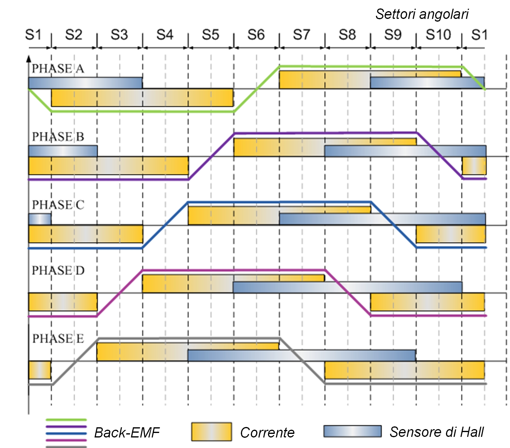
An orientation logic, enslaved to the position sensor, generates the current control. In PM-BLDC motors, the current is controlled in phase with the trapezoidal voltage induced by magnets (back-EMF), to generate constant torque, as shown in Figure 5.
Each phase shares in the overall torque with a proportional contribution to its own current. «An outer ring –Professor Tursini adds– adjusts the motor speed, drawn by the mechanical sensor, still with PI regulator.
A redundant communication bus allows phase microcontrollers to share the speed control, the position measurement and other useful information to equalize the control among phases».
The power stage of each module is composed by a single-phase inverter, as per Figure 6.
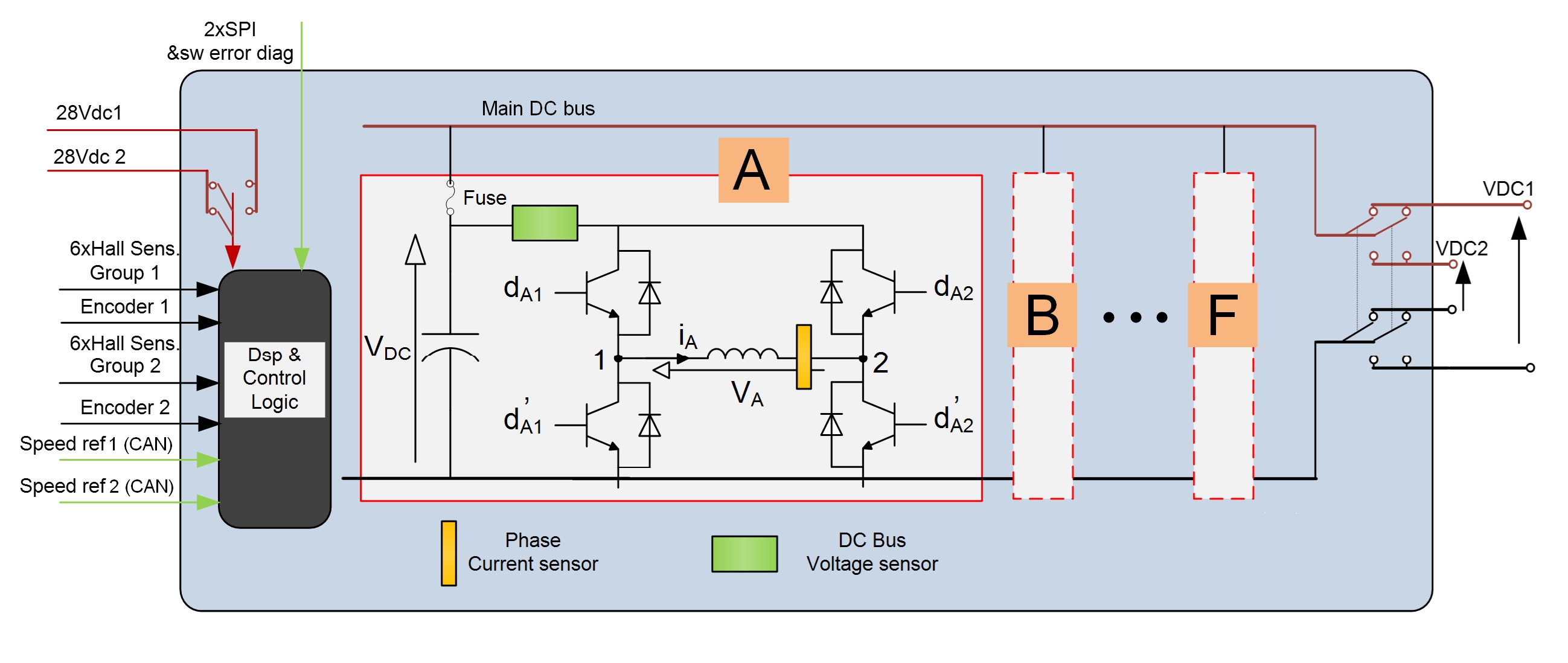
In case of fault on a motor phase, the latter is disconnected by cutting off the power switches of the correspondent single-phase inverter.
«The short circuits on inverter branches –Professor Tursini adds – are primarily managed in hardware, detected by the drivers of power switches and reported to the microcontroller that provides for controlling the concerned branch in cut-off.
The short circuits persisting on the inverter and the short circuit on the levelling condenser are protected by the fuse cut-off at the stage input, which equally cuts out the phase but avoids the short circuit of the power DC bus».
Fault tolerance
The architecture of the fault-tolerant drive allows the control adaptation in automatic in case of loss or cut-out of one or more phases caused for failure, as we can assess in Figure 7.
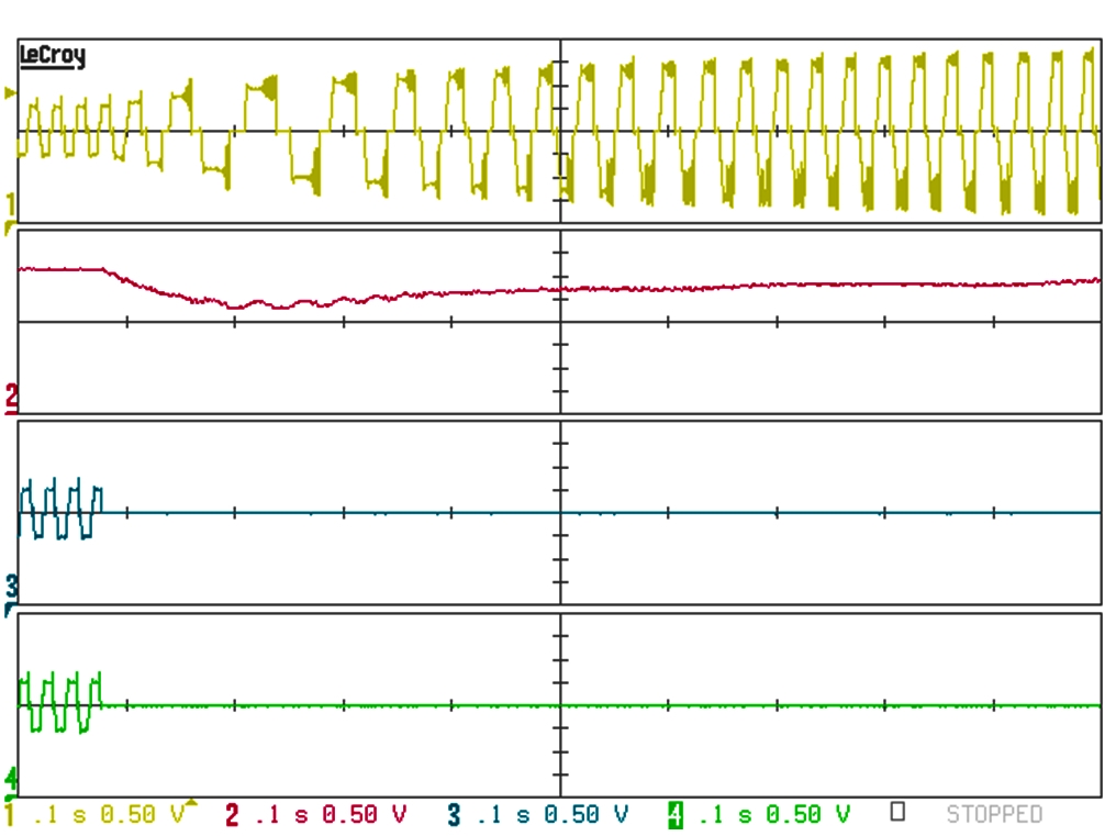
«In such eventuality in fact –Professor Tursini highlights – we have a transient reduction of the produced torque and a consequent decrement of speed. The latter, surveyed by speed regulators, results in a rise of the current control for sound phases, which restores the value of the average produced torque to the pre-fault level and the speed to the controlled level».
Owing to the loss of phases caused by failure, the torque ripple around the average value increases, hand in hand with the number of missing phases and with the adjacency of their angular arrangement in the motor, but this aspect is secondary in a “safety critical” system. «The fault-tolerant drive–Professor Tursini confirms – must then be sized fixing in the specifications the number of phases that can be lost and considering the overload of sound compensating phases». If we assume the torque/current relation as linear, the overload factor of a fault-tolerant motor is given by:
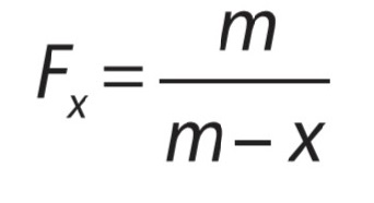 Where m is the number of phases of the motor and x is the number of inactive phases (cut off) owing to faults or corrective fault actions. For a 5-phase motor, it is valid F1 = 1.25 and F2 = 1.66 respectively for one or two missing phases. «Actually –Professor Tursini adds–aeronautical actuators are sized to exploit magnetic circuits at best. Consequently, the active phases operate in conditions of high saturation in case of fault and the current overload is higher. The Finite Element electromagnetic analysis allows obtaining more accurate indications concerning this since the design phase».
Table 2 reports, as example, the results of the Finite Element analysis for the FA actuator, including the torque/current ratio (TCR) in the operation with sound phases and with fault.
Guaranteed reliability requisites
What reported validates that modular fault-tolerant drives already represent an immediately feasible solution to guarantee the reliability requisites of aeronautical applications. Prototypal studies and systems already in use in aircrafts confirm it. «Compared to hydraulic and pneumatic systems –Professor Tursini ends– electric drives offer more user-friendliness in installation and maintenance, reduced overall dimensions and weights, hypothetically allowing the reduction of fuel consumption and of consequent emissions. This is a more and more central aspect in a globalized society taking care of environmental issues. Since 2008, the European Commission, in partnership with the major European aerospace industries, has promoted and funded “Clean Sky” Consortium, technological initiative for an “ecologically favourable” evolution of the air transport».
FOCUS ON RESEARCH
Marco Tursini was born in 1960 in L’Aquila province and graduated in Electrical Technology Engineering at L’Aquila University in 1987. In the same year, he started his scientific collaboration with L’Aquila University where he is currently Ordinary Professor of Power Converters, Electrical Machines and Drives and President of the Master Didactic Area Council in Electrical Engineering. In his career, he carried out research activity by the Swiss Federal Institute of Technology in Lausanne and by Nagasaki University.

Since the early Nineties, he has been manager of numerous research projects, in both industrial ambit (Texas Instruments, Indesit, Gefran, Denso, Umbra Cuscinetti) and in national funded projects (MIUR, PRIN, PON, Industria 2015) and European (Clean Sky). His interests concern the sector of electric machines and drives, with specific focus on modelling, simulation and control, “sensorless” drives, failure analysis and diagnostics, “realtime” simulation and rapid prototyping techniques. In this ambit, he is author of over 140 scientific publications. IEEE member and reviewer of numerous international journals and conferences, since 2011 he has been member of the Editorial Board of the international review “Electric Power Components & Systems”. In 2014 he promoted the birth of “R13 Technology” spinoff of L’Aquila University in the sector of industrial electronics, electric motors and drives, automation and measuring systems.