

The paper presents a procedure for the design of a Permanent Magnet Synchronous motor for electric city scooter. The procedure combines a preliminary analytical evaluation of motor size together with a fine investigation by using the Finite Element Method approach. The paper explains the design choice that have been made to satisfy the typical main requirements for an electric vehicle.
PM synchronous motor for electric city scooters
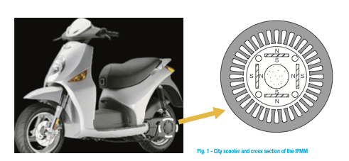
The increasing cost of oil and the negative impact of the combustion process on the environment resulted in an increasing interest of vehicle industry and governments around the world in developing electric and hybrid vehicles: in this context, the electric city scooters (figure 1) could play a significant rule since in the last years they have had a considerable growth.
The research in this field consists of designing efficient and compact electric drives with special requirements. The motor is the main component of an electric vehicle and the specifications are different from conventional ones used in other industries. The typical main requirements are the following:
- high torque-to-ampere and torque-to-volume ratios to minimize the inverter cost and the drive overall dimensions;
- wide flux-weakening region, to minimize the drive power rating in spite of a wide speed range;
- good overload capability;
- high efficiency to increase the vehicle autonomy;
- 5) simple manufacture for a cost-effective end product.
Conventionally, the induction motor has been used for electrical vehicle traction due to its robustness, low cost and overload capability. However, the control of the induction motor is quite complicated and its size is hard to reduce for a given power range. The Interior Permanent Magnet Synchronous Motor (IPMM) can be considered as a good choice, thanks to the decreasing price of Permanent Magnets (PM) during the last decade: this aspect has represented a good opportunity for the design of cost effective, compact and efficient traction drive for electric vehicles. The typical cross section of the rotor is shown in figure 1.
This motor requires an accurate speed control with a current-regulated inverter: that is crucial to the efficiency and operation of the electric vehicle.
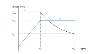
In this paper the design of the IPMM is carried out for achieving a suitable torque-speed characteristic, defined from zero to base speed (VB) as “constant-torque region” and from base to maximum speed (VMAX) as “constant-power region” in the flux-weakening operation (figure 2).
The proposed procedure combines a preliminary analytical evaluation of motor size together with a fine investigation by using the Finite Element Method (FEM) approach. It can be divided into two steps as illustrated in the follows.
1) The first step deals with the characterization of the motor parameters as well as of the inverter power ratings with the purpose to cover the desired performance. Then the main motor dimensions are carried out starting from these parameters and imposing the thermal and magnetic limits.
2) Once the motor dimensions are fixed, a FE analysis tests the motor performance in the whole speed range, with the aim of evaluating and refining the design.
The design concerns a scooter for 2 passengers, equivalent to a 100 cc. traditional scooter, with the following specifications: weight of the scooter 140 kg, rated speed 30 km/h, maximum speed 70 km/h, maximum road grade 20% and an autonomy at maximum speed of about 50 km.
The value of the autonomy is referred to a continuous duty. In an urban cycle there is an hard use of accelerator and brake, and in this case we can obtain a larger autonomy thanks to the regenerative braking.
In this contest an interior PM synchronous motor has been designed that allows to drive, by a reducer, the back wheel. The motor is fed by Inverter that is linked to the batteries: a suitable control strategy allows to optimize the motor performance in a wide range of speed.
Design of the IPMM for the city scooter
A software has been developed in order to calculate the “electromechanical” requisites (electric motor and batteries) of the scooter. The structure of the software is shown in figure 3.
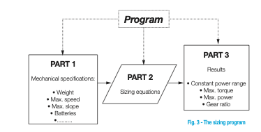
Starting from the above listed specifications and using appropriates sizing equations, the program calculates the performances in terms of torque-constant range and power constant range (figure 2), the transmission ratio between the motor and wheel and the size of batteries. In this analysis, a DC voltage of 84 V and maximum phase current of 90 A have been imposed.
For this specific application, the electric motor should have a power of about 5 kW with a base speed of 2600 rpm (corresponding to a speed of scooter of about 30 km/h) and a maximum speed of 5800 rpm (corresponding to 70 km/h). These results have been used for the next design of the electric motors.
The IPMM design has been carried by imposing the thermal and magnetic limits. The main motor dimensions are reached by solving a system of non-linear equations. From the system of equations, the rotor diameter, stack length, numbers of turns, PM dimensions and air-gap length can be obtained. A sintered NdFeB magnet with favourable high-temperature characteristics has been chosen in order to achieve the lowest possible machine mass and volume.
By adopting a simplified thermal lumped network, the copper over temperature has been estimated as a function of motor dimensions, electric loading, the stator copper and specific thermal resistances.
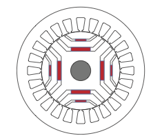
In order to satisfy the requirements on motor power and above all increase the torque-to-volume ratio, a solution with two PMs per pole has been chosen (figure 4). The final design presents the following data: 4 pole, 36 stator slots, 120 mm stack length, 130 mm outer stator diameter, 80 mm inner stator diameter, 18 turns per phase. The motor weight is about 11 kg.
The motor is fed by an inverter and the control strategy is based on the well known “vector control” approach. The incoming torque command is mapped into commands for the direct and quadrature axis currents (Id, Iq) according to the following equation:
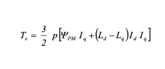
where yPM is the PM flux, p the pole pairs, Ldand Lq are the d and q axis inductances respectively.
The current commands in the rotor d-q reference frame (d.c. quantities for a constant torque command) are then transformed into the instantaneous sinusoidal currents for the individual stator phases, using the rotor angle feedback (by a rotor position sensor) and the basic inverse vector rotation equations.
Starting from the motor data, the Finite Element Method has been used for the analysis of the IPMM for an accurate prediction of the motor performance in order to take into account the saturation phenomena, the right flux distribution in all the part of the magnetic circuit and the cross- magnetization effects. In this study, the IPMM has been simulated by a 2-D Finite Element model by a commercial software, and the analysis takes into account the influence of temperature on the PM performance, that affects also the motor torque.
Moreover, the FE model allowed to analyze the motor performance at different d-q axis currents values and several relative positions between stator and rotor.
The motor performance
Several FE simulations have been carried out with different values of axis currents (Id, Iq) that correspond to a maximum phase current values of 90 A. In table 1 are shown the performance with reference to the base speed (vb) of 2600 rpm and maximum speed (vM) of 5800 rpm. In the first case the torque is 18 Nm and power is about 5 kW, with an efficiency of 90% and a power factor of 0.89. The maximum speed range is more than 2 times the rated speed and the efficiency is 91%: this results confirm the goodness of the proposed design.
| vb = 2600 rpm – (Id=-63.64; Iq=63.64) | vM = 5800 rpm – (Id=-87.33; Iq=21.77) | |||
| Torque Nm | 18.0 | Torque Nm | 9.2 | |
| Power W | 4900 | Power W | 5590 | |
| Frequency Hz | 87 | Frequency Hz | 193 | |
| Efficiency % | 90 | Efficiency % | 91 | |
| Power factor | 0.89 | Power factor | 0.97 | |
| Speed of scooter km/h | 30 | Speed of scooter km/h | 69 |
The flux density is shown in figure 5 with reference to one pole of the machine.
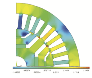
The maximum flux density in the teeth and yoke do not exceed 1.7 T, while in the rotor is about 1.5 T.
The batteries has been sized taking into account a DC voltage of 84 V and a maximum current of 90 A: the Nickel-Metal Hydride (Ni-MH) modules has been chosen, with enhanced specific energy and energy density, usually employed in the electric vehicle.
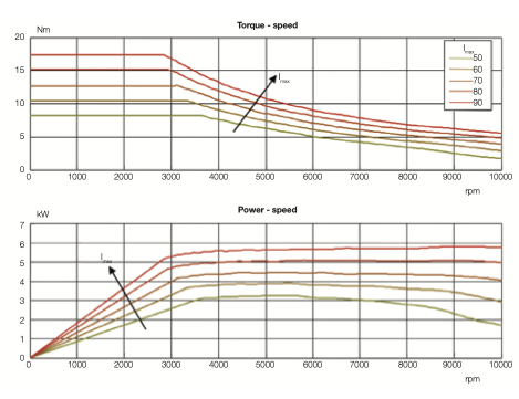
The calculated total weight of batteries is about 35 kg. The torque-speed and power-speed characteristics of the IPMM are shown in figure 6 for different current values. It is evident a wide speed range at maximum torque from zero to 2600 rpm; then, the torque reduces in the “flux weakening region” and the operation in this region is limited by the rated current and the rated voltage.
Conclusions
The design procedure for the PM synchronous motor has been described and a machine has been designed for applications in a city scooter. Owing to their low inertia, high power-to-weight ratio and acceleration performance the IPMM can represent a valid alternative for the electric vehicles, respect to the traditional induction motors or direct current motors.
The proposed design procedure, that combines a preliminary analytical evaluation of motor size together with a fine FEM analysis, has allowed to design a IPMM motor with two PMs per pole, giving good results in terms of torque-to-volume ratio, efficiency and power factor.
(by Marco Villani, Department of Industrial and Information Engineering and Economics, University of L’Aquila, Italy)


