

A detailed methodology for the NVH analysis of an electric axle (EDU), which integrates: the plotting of mechanical and electric orders; the modal analysis and the flexible multi-body simulation.
NVH analysis of an electric axle
The noise emission of an electric axle (EDU) is the result of the high-frequency vibrations generated by the electromagnetic forces on the rotor, by the meshing of toothed wheels (whine) and by the presence of the inverter. Unlike traditional internal combustion systems, where the low-frequency noise tends to mask high-frequency disturbances, EDU features lower sound pressure levels concentrated in higher frequencies, which are more easily perceptible and annoying. The article presents a methodology for the vibroacoustic analysis of an EDU, including the plotting of mechanical and electrical orders on a Campbell diagram, the determination of mode shapes and the flexible multi-body simulation to evaluate the forced response of the system. Particular attention is paid to the comparison between low contact ratio gears (LCR) and with high contact ratio (HCR), assessing parameters such as the peak-to-peak transmission error (PPTE), meshing forces, the loads on bearings and the equivalent acoustic radiated power (ERP).
Introduction
The automotive industry is increasingly urging towards the electric mobility, adopting propulsion systems that reduce the consumption of fossil fuels and “tank-to-wheel” emissions. The adoption of an EDU implies a significant reduction of the noise emission level both inside and outside the vehicle, in particular at low speeds. However, the new acoustic setup is characterized by the presence of distinct “tones” arising from the electric motor, the transmission and the inverter. For this reason, NVH simulations are fundamental in design phase, permitting a correct integration of the component into the vehicle and identifying possible criticalities.
Analysis, methodology and case study
The strategies to define acoustic targets can be implemented both at system level (by synthesizing the sound pressure level inside the passenger compartment by means of transfer functions) and at component level, by analysing thoroughly the individual contribution of subsystems. Numerous studies carried out by specialized institutes (for instance, the “Gear Lab” of the Ohio State University, the “Gear Research Center (FZG)” of the Technical University of Munich and the “Laboratory of Vibrations and Powertrain” of the University of Modena and Reggio Emilia, Italy) have contributed in the definition of NVH optimization parameters for electric motors and transmissions.
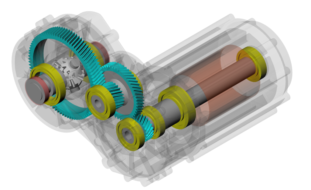
The EDU under examination is characterized by an electric motor and by a single-speed transmission with two cylindrical reduction stages (figure 1).
The power is delivered by a permanent magnet synchronous motor; the coupling between the motor and the transmission occurs by means of a spline. The electric machine is characterized by 2p = 6 poles and by s = 36 stator slots. The second stage crown is integral with the differential body, not modelled in this article.
In table 1 the macrogeometric parameters for two sets of gears are listed: LCR (with low contact ratio) and HCR (with high contact ratio, that is to say ea > 2). In both cases the meshing order is 23.00 for the first reduction stage and 9.98 for the second reduction stage. The order 1 is referred to the rotor of the electric machine.
| Meshing parameters | Stage 1 | Stage 2 | |||
| Wheel 1 | Wheel 2 | Wheel 3 | Wheel 4 | ||
| Number of teeth | z [-] | 23 | 53 | 23 | 89 |
| Helix angle on the primitive | an [°] | 30 | 15 | ||
| Normal pressure angle | an [°] | 20 | 20 | ||
| Normal Module | mn [mm] | 2.5 | 2.6 | ||
| Profile shift factor | x* [-] | 0.0163 | -0.6682 | 0.4706 | -0.6659 |
| Band width | b [mm] | 25 | 23 | 40 | 38 |
| Interaxis | a[mm] | 107.99 | 150.22 | ||
| Meshing order | GMF | 23.00 | 9.98 | ||
| LCR gearing profile | h*fP/ρ*fP/ h*αP | 1.25/0.38/1.00 | 1.25/0.38/1.00 | 1.25/0.38/1.00 | 1.25/0.38/1.00 |
| HCR gearing profile | h*fP/ρ*fP/ h*αP | 1.80/0.19/1.35 | 1.60/0.29/1.60 | 1.60/0.29/1.35 | 1.60/0.29/1.45 |
| LCR transverse coating | [-] | 1.43 | 1.53 | ||
| HCR transverse coating | 2.05 | 2.10 | |||
| Helix coating | [-] | 1.46 | 1.20 |
Plotting of orders and modal analysis
The first phase of the methodology provides for:
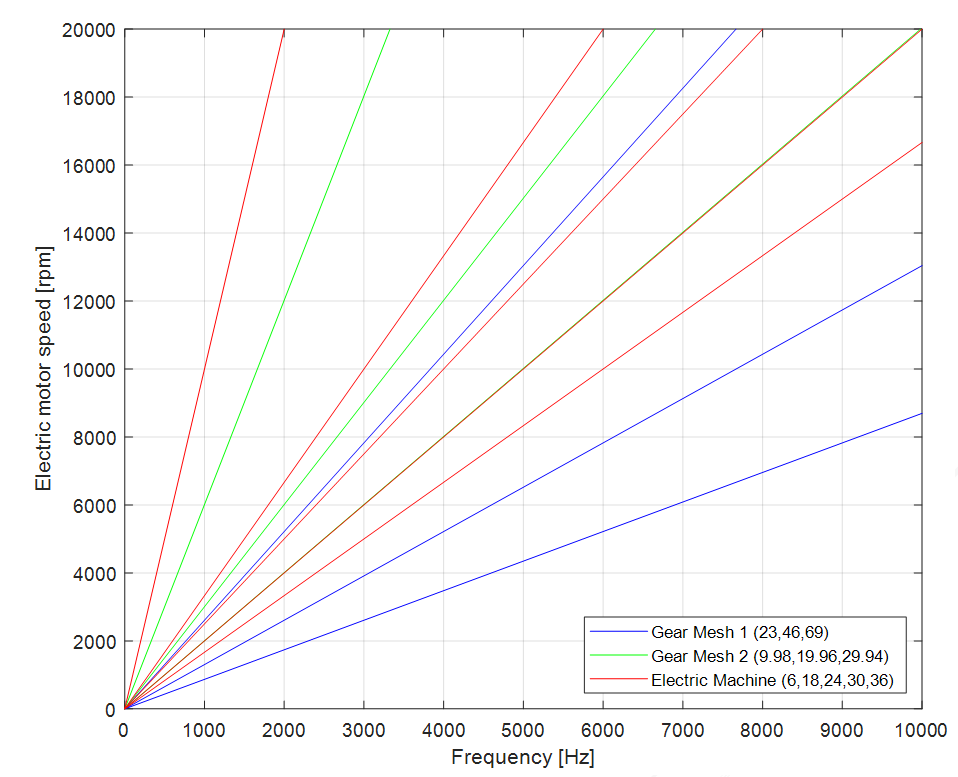
- Plotting of mechanical and electric orders on an extended Campbell diagram, which highlights both the resonances of the system and the speed of electric machine adopted in multi-body simulations.
- Calculation of EDU mode shapes, which allows identifying the vibration modes of the system. The first natural frequencies obtained, for instance, are between 238 Hz and 719 Hz, providing a basis for the prediction of possible interactions between the forcing orders (meshes, electric machine, inverter) and the structural resonances (figure 2).
Multi-body modelling and forced response simulation
Afterwards, the electric axle is modelled as a flexible multi-body system. Using the Craig-Bampton modal condensation technique, the model allows studying the forced response of the system. In this context, the gear parameters can be directly imported from KISSsys to grant consistency with the design phase.
To evaluate the NVH improvement, two configurations of gears are compared:
- LCR gearing (Low Contact Ratio): standard profile according to the ISO-53 regulation.
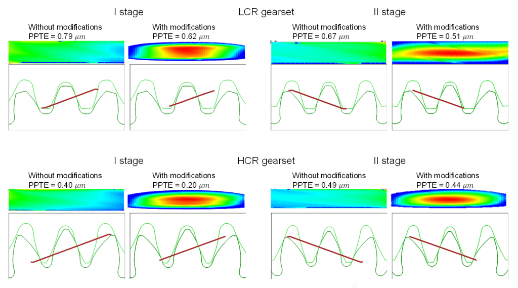
- HCR gearing (High Contact Ratio): characterized by a high contact ratio (ea > 2) and designed with microgeometric modifications, such as longitudinal cambers, head reliefs and helix angle variations, in order to reduce the PPTE and meshing forces (figure 3).
Comparison parameters are the following:
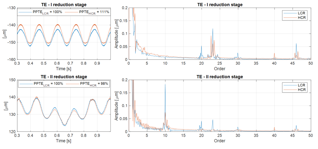
- (PPTE) transmission error: analysed in the domains of time and frequency for both reduction stages.
- Meshing forces: simulations show a significant reduction of the harmonic content for the HCR profile.
- Loads on bearings: they are lower in terms of peak-to-peak and harmonic content for the HCR configuration, being rotation orders (for instance 1.00 for the input shaft, 0.48 for the intermediate and 0.11 for the output) mainly influenced by misalignments and backlashes caused by the housing stiffness.
Constrained modal analysis
The modal analysis of the EDU is carried out on pads to evaluate the vibration modes of the system. The first ten natural frequencies are listed in table 2.
| Frequency [Hz] | |||
| Mode 1 | 238 | Mode 6 | 487 |
| Mode 2 | 273 | Mode 7 | 577 |
| Mode 3 | 296 | Mode 8 | 589 |
| Mode 4 | 387 | Mode 9 | 639 |
| Mode 5 | 412 | Mode 10 | 719 |
The goal of this analysis is predicting the interaction of the main forcing orders (meshes, electric machine and so on) with the system resonances. Figure 4 shows the extended Campbell diagram: when the resonances frequencies intersect the excitation orders, an amplification of the response is expected.
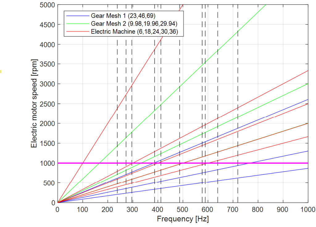
Fig. 4 – Extended Campbell diagram, where are included the system resonances and the speeds of electric machine adopted in multi-body simulations
Forced response analysis
The forced response is calculated with the aid of Recurdyn software, where meshing parameters can be imported from KISSsys.
The results of the multi-body simulation performed with flexible housing are reported below. The transmission error is analysed in figure 5 for both reduction stages, in time and frequency domains. The magnitude of the meshing order is lower for HCR gearing. Sidebands appear, because the meshing frequency is modulated by shaft rotation orders. The rotation orders of shafts, calculated through the transmission ratios of both stages, are respectively 1.00 for the input shaft, 0.48 for the intermediate shaft and 0.11 for the output shaft. The magnitude of these orders is similar for both LCR and HCR gearings, since they are mainly due to the presence of misalignments induced by the housing stiffness and by bearing clearances.
Meshing forces are shown in figure 6 and confirm a significant reduction in the harmonic content of the HCR gearing compared to LCR gearing.
Equivalent radiated acoustic power (ERP)
The equivalent radiated acoustic power (ERP) is defined as follows:
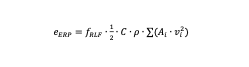
Where fRLF is the loss factor, C is the speed of the sound, ρ is the density of the material carrying the vibrations, for instance air, Ai is the area of the i-th surface and vi is the normal component of the surface velocity on the i-th surface. Further details are available in [36].
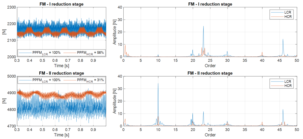
Fig. 6 – Meshing force and harmonic content – rigid housing
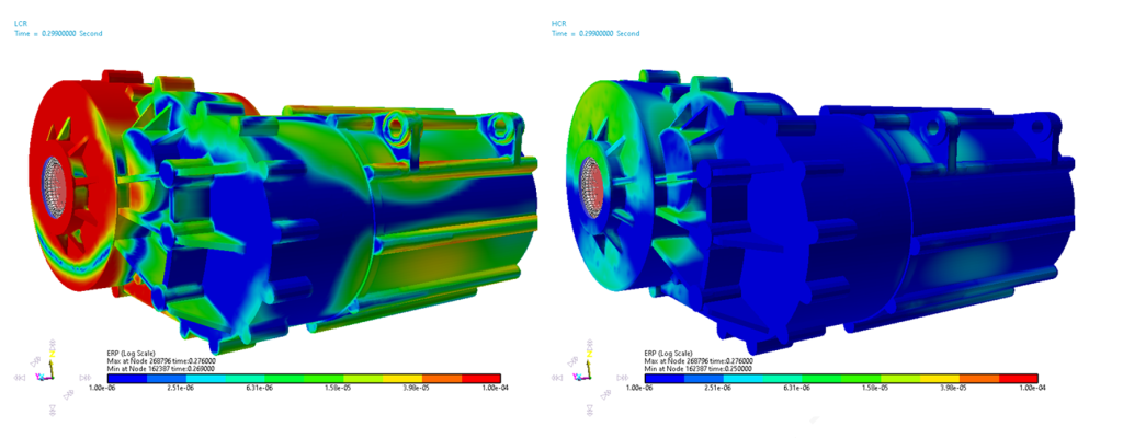
Figure 7 presents the comparison between LCR and HCR teeth in terms of ERP: the reddish coloured regions are representative of a more intense sound radiation, which confirms the previous discussions on the improvement of the acoustic performance by adopting high-contact ratio teeth.
Moreover, the map in figure 7 is extremely useful to investigate the contribution of each region of the housing to the total sound emission, and to guide design modifications (for instance, local stiffening by means of ribs).
The results of multi-body simulations, carried out with a flexible housing, highlight:
- Transmission error: The time and frequency simulation show a lower amplitude of the meshing order for the HCR gearing, despite the appearance of sidebands due to the modulation of rotation orders induced by the housing stiffness and by bearing clearances.
- Mesh forces: Simulations (figure 6) confirm a significant reduction in the harmonic content of the mesh force for the HCR configuration.
- Loads on Bearings: comparison of the spectra of forces acting on bearings (figure 6) indicates that the HCR configuration results in lower loads, contributing to higher reliability and lower mechanical stresses.
- (ERP): ERP maps (figure 7) clearly highlight that the critical regions of the housing are less subjected to an intense sound radiation in the HCR configuration, suggesting possible targeted interventions such as local stiffening through the application of ribs.
Conclusions
The article has illustrated a detailed methodology for the NVH analysis of an electric axle (EDU), which integrates the plotting of mechanical and electric orders, the modal analysis and the flexible multi-body simulation. The comparison between gears with standard toothing (LCR) and high contact ratio (HCR) pointed out a significant improvement in acoustic performances: a reduction in PPTE, meshing forces and bearing loads was recorded, accompanied by a decrease in equivalent radiated acoustic power.
Further modifications to the housing structure, in order to further minimize the ERP value, will be the subject of future analyses and design interventions.
by Davide Marano, GearLab AG


, which integrates: the plotting)