

Mechanical gears are extensively used for speed change and torque transmission, to match the operating speed of prime-movers to the requirements of their loads, since it is usually more cost and weight effective to employ a high-speed electrical machine together with a gearbox to transform speed and torque.

Mechanical gears (figure 1) are used in several industrial, automotive and aerospace applications. Although the torque density of the mechanical gears is quite high, they have negative factors concerning:
- Lubrication
- Regular maintenance
- Cooling
- Noise
Lubrication is essential to the operation of mechanical gears and allows to reduce the energy lost to friction, the amount of wear and tear on the gears themselves. Mechanical gearing is susceptible to this wear and tear over long periods of time, even with intensive lubrication. Consequently, these gears will require regular maintenance and upkeep to be kept working at peak efficiency. Industrial lubricant is costly; however, if lubricant is not used, the repair cost for mechanical gearing systems can be extremely expensive.
All of the complications involved with the lubrication of mechanical gears can be circumvented with the use of Magnetic Gears (MG); this is because magnetic gears are not physically connected. Since there is no contact between gears, there is no loss of energy to friction, no long-term wear and tear, no transfer of mechanical vibrations, and ultimately, no need for lubrication. All of these benefits make magnetic gearing especially appealing to those looking to reduce, and potentially eliminate, costs due to the maintenance, repair, and lubrication of gearing systems.
Magnetic gears, therefore, are clearly the better choice when considering the negative factors which limit mechanical gears in lubrication, maintenance, and long-term operation and have a physical isolation between input and output shafts, high torque density and higher reliability.
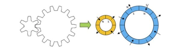
The magnetic gear uses permanent magnet (PM), mainly rare earths magnets (NdFeB), instead of the teeth for mechanical gear to transmit torque between an input and output shaft without mechanical contact by interactive magnetic force through small airgap between gears: figure 2 shows a schematic view of magnetic gear.
Magnetic gears with PM have a very simple structure with performance comparable with that of mechanical gears and the following advantages:
• no lubrication required for the gears;
• reduced maintenance and greater reliability;
• overload protection;
• reduced mechanical stress;
• physical decoupling between the input shaft and output shaft;
• no losses due to mechanical contacts other than those caused by bearings;
• minimal vibrations;
• high efficiency;
• high torque density;
• wide speed ratio.
The advantage of using magnetic transmission is that it has an efficiency greater than 95% and a transmission range from 1:1 to 1:15. Moreover, a transmitted torque density of 50¸100 kNm/m3 can be obtained which is comparable with that of mechanical gear.
The two rotors with surface PMs replace the mechanical gearbox, ensuring the same transmission ratio. With this type, however, most of the permanent magnets are inactive during operation and do not contribute to torque transfer. Furthermore, the volume occupied by the entire gear is high because the two rings are separated from each other.
The types of magnetic gearboxes currently being studied are as follows:
• axial motion gearbox
• planetary gearbox
• coaxial magnetic gearbox
• cycloidal gearbox
• PDD (Pseudo Direct Drive) gearbox
The focus of this paper is on “coaxial magnetic gearboxes” with PM without windings (CMG). This solution is perfectly analogous to a mechanical reducer and allows to simply vary the number of revolutions (and therefore the torque) according to a fixed “reduction ratio”: it must therefore be coupled to a prime mover (internal combustion engine or electric motor).
Coaxial magnetic gear CMG
A simple type of coaxial magnetic gear reducer (without windings) consists of three rings as shown in figure 3: two of these rings (rotors) have surface PMs (with radial magnetization). Efficiency is high as there are only losses due to eddy currents in the ferromagnetic core and permanent magnets.
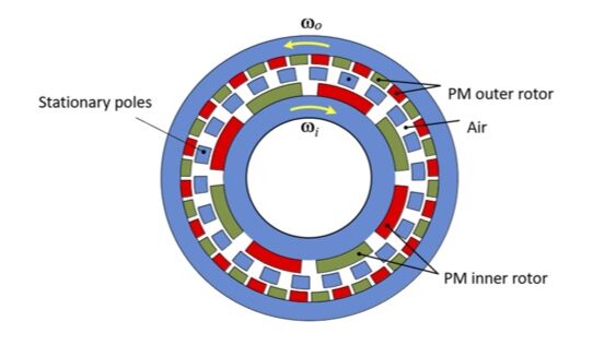
The outer ring consists of a greater number of magnets, while the inner ring has fewer magnets. The third (central) ring is located between the two PM rotors and consists of ferromagnetic bars inserted into a non-magnetic mechanical structure made of resin or steel, whose function is to modify the magnetic field generated by the PMs. The innermost ring is connected to the motor shaft, while the outermost ring is connected to the output shaft. The gearbox therefore consists of two rotors (and therefore two shafts): one high-speed and one low-speed.
In addition to rotating at different speeds, the two rotors rotate in opposite directions, with the inner rotor rotating counter-clockwise and the outer rotor rotating clockwise. This is due to the presence of ferromagnetic bars (the number of which must be equal to the sum of the number of pole pairs of the two rotors), in which currents are induced by the permanent magnets on the inner rotor.
The speeds of the two rotors differ due to the different pole pairs on the two rotors.
The operation of the magnetic gear is based on the modulation of the magnetic field produced by the pi pole-pairs PMs rotor (inner rotor) by the ns pole pieces. The modulated field interacts with the PMs rotor with po pole-pairs in order to transmit torque to the load (outer rotor) at different speed.
The number of ferromagnetic pole pieces is: ns = pi + po
The choice (ns = pi + po) allows to guarantee the highest torque transmission capability of the gear.
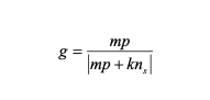
The number of pole-pairs in the space harmonic flux density distribution produced by either the high or low speed PM rotor is:
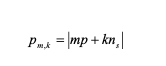
where: m = 1, 3, 5,….∞ and k = 0, ±1, ±2, ±3,….. ±∞.
The rotational speed of the flux density space harmonics:
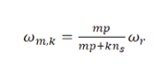
where ωr is the rotor mechanical speed.
The speed of the space harmonics due to the introduction of the steel pole-pieces, is different to the speed of the rotor which carries the PMs if k ≠ 0.
Therefore, in order to transmit torque at a different speed, the number of pole-pairs of the other PM rotor must be equal to the number of pole-pairs of a space harmonic for which k ≠ 0. This means that the transmission ratio is given by:
When comparing the efficiency between mechanical and magnetic gears, one must first understand some basic gearing nomenclature. Gear ratio, for instance, is an important term that refers to the ratio of angular speed of the input shaft over the angular of the output gear. This value can also be determined by simply taking the ratio of the output torque to the input torque. If a coupling of gears has a high gear ratio, this means a small force is being applied to the system, but a comparatively large force is coming out. Thus, a high gear ratio can lead to better efficiency. Efficiency, in its most basic form, can be expressed as the output shaft power divided by the input shaft power.
Magnetic gears can reach gear ratios comparable to that of mechanical gears, but this is not the primary concern in regards to overall efficiency. The loss of efficiency in a mechanically geared system results chiefly from the friction of gear contact. Another factor to be considered when comparing mechanical and magnetic gearing is torque density. Torque density is simply the output torque divided by the volume of the gear coupling. A mechanically geared system often occupies a large volume, while magnetic radial coupling is smaller in comparison.
A case study
The CMG gearbox has the following parameters:
pi = 3, po = 13, ns = 16, and a gear ratio of 4.3.
The main data of the magnetic gears are listed in table 1. The stator lamination is a traditional 800-50A electrical steel, 0.50 mm thickness, and NdFeB permanent magnet, for the high and low speed rotors.
| Outer radius mm | 190 |
| Shaft radius mm | 100 |
| Axial length mm | 100 |
| PM thickness – inner rotor mm | 10 |
| Pole pieces thickness mm | 10 |
| PM thickness – outer rotor mm | 10 |
| Airgap length mm | 1.0 |
| Electrical steel | FeSi – 800-50A |
| Permanent magnet | NdFeB – N38SH |
| Operating temperature °C | 70 |
Table 1 – CMG data
The performance of the magnetic gears have been analyzed by using the Finite Element method that gives accurate results taking into account the geometric details and non-linearity of magnetic materials. A versatile 2D model has been developed, and the torque has been calculated for different rotors positions.
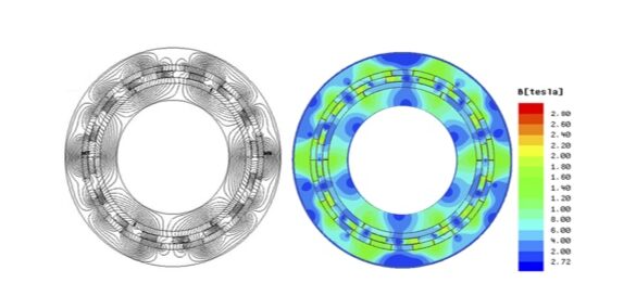
The flux lines and flux density distributions are shown in figure 4, while figure 5 shows the radial component of the flux density and space harmonics spectrum in the air-gaps adjacent to the inner and outer rotors.
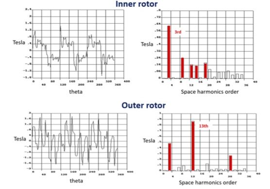
In this case the largest harmonics are respectively the 3rd and 13th for the high and low speed rotor. Figure 6 shows the electromagnetic torque profiles with rotors positions which is exerted, respectively, on the inner and outer rotors; a transmitted torque density of about 70 kNm/m3 can be achieved.
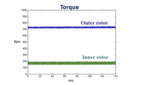
The speed of the inner rotor is 5500 rpm and 1270 for the outer rotor. The torque value is 727 Nm for the outer rotor and 167 for the inner rotor, with a gear ratio of 4.3 (table 2).
| Speed (rpm) | Torque (Nm) | |
| Inner rotor | 5500 | 167 |
| Outer rotor | 1270 | 727 |
Table 2 – Torque and speed
Conclusions
The magnetic gears are clearly a good choice when considering the negative factors which limit mechanical gears in lubrication, maintenance, and long-term operation and have a physical isolation between input and output shafts, high torque density and higher reliability.
The magnetic gears use permanent magnets – mainly rare earths magnets – instead of the teeth for mechanical gear, to transmit torque between an input and output shaft without mechanical contact by interactive magnetic force through small airgap between gears.
This paper focused on a particular type of magnetic gear, the “coaxial magnetic gearbox”, which has performance comparable to that of mechanical gears. The outer rotor has low speed and high torque, as its number of poles is greater than the number of poles of the inner rotor, which has high speed and low torque.
The coaxial magnetic gear has a very simple structure and the advantage of a smaller volume compared to other magnetic gear types, allowing for a transmitted torque density of 50÷100 kNm/m3, and it can therefore be a valid alternative to traditional mechanical gears for industrial and automotive applications.
(by Marco Villani – Department of Industrial and Information Engineering and Economics, University of L’Aquila, Italy)


