
In the context of the Paris Agreement on Climate and of the transition towards the electric mobility, three big players have signed a Memorandum of Understanding for the establishment of a Consortium of Interchangeable Batteries for motorcycles and light electric vehicles. They are Honda, KTM, Piaggio and Yamaha Motor, convinced that a standardized system of interchangeable batteries will enhance the broad use of light electric vehicles and will share in the management of a more sustainable lifecycle management of the batteries used in the transport sector.
The goal of the Consortium, which will start its activities in May 2021, will consist in defining the standardized technical specifications of the interchangeable battery system for vehicles belonging to the “L” category; mopeds, motorcycles, tricycles and quadricycles. The 4 founder members of the Consortium, working with all concerned companies and national, European and international standardization bodies, will be involved in the definition of international technical standards.
“The global electrification effort to reduce CO2 emissions on a planetary scale – declared Noriaki Abe | Managing Officer, Motorcycle Operations, Honda Motor Co., Ltd – is in acceleration phase, especially in Europe. For the widespread adoption of electric motorcycles, problems like the transfer distance and recharge times, must be taken into account, and interchangeable batteries are a promising solution».
Interchangeable batteries? Teaming up for the electric propulsion

Driver for 30%-smaller drive systems

The last overseas news regarding the new developments of the technology for electric motors concern Texas Instruments.
The multinational has recently presented a driver for brushless DC motor (BLDC) Degree 0, highly integrated, for the drive systems of high-power 48 V motors, such as traction inverters and starter motors /generator of mild hybrid electric vehicles (MHEV). What are its outstanding peculiarities?
DRV3255-Q1 can help designers in reducing the sizes of motor systems by even 30%, providing the highest gate drive current in the sector for better protection and higher output power. Complying with the most severe safety requisites, the new motor driver has been designed according to the development process of TI functional safety certified by TÜV SÜD and shares in reaching the integrity level of ASIL D automotive safety. Further information are available on the site www.ti.com/DRV3255-q1-pr-eu.
The reduction of the board footprint is possible up to 30%: DRV3255-Q1, driver for 48-V three-phase BLDC motor integrates the active high-side and low-side short circuit logic, which eliminates external transistors and the control logic. Through the active short circuit logic integration and the dynamic response to failures, the new motor driver allows designers not only to simplify their designs but also to supply up to 30 kW of motor power, so decreasing the board footprint and the cost in bill of materials for drive systems for 48-V motor.
Dynex Integrated Power Unit (IPU)

Dynex Semiconductor has developed a range of power inverters for automotive applications. With the units being suitable for use with both hybrid and fully electric vehicles driving multiple types of AC motor, Dynex Semiconductor inverters are of compact design with high efficiency and leading power to weight ratio.
The Features of the seminconductors of Dynex are severals. They are optimised for EV and HEV application, the bespoke IGBT power module is designed specifically for HEV/EV application, the double-sided cooling package for IGBT module increasing thermal performance and power density, there is the active gate driver technology with di/dt control. Moreover, there is wide input voltage range up to DC470V, very wide range high system efficiency, advanced and reliable motor control, selection of optimised motor control algorithms for different motor technologies, AUTOSAR compliant software development and emphasis on functional safety according to ISO26262.
A compact, clean, solder-free solution

Pioneer in the sector of electric connections, in the late Eighties TE Connectivity invented solutions to replace the old solder process technology for magnet wire connections. The company, multinational worth 14 billion dollars, supplies all-round solutions not only for the electric connection part but also for plastic insulation and assembling.
MAG-MATE connector with Multispring pin is a combination of two key technologies that eliminate the customer’s need to solder. It provides the ability to directly connect magnet wire to a Printed Circuit Board with no solder. Traditionally, the process is to solder magnet wire to a pin, assemble the PCB to the pin, and then solder the PCB to the pin. But now no more, thanks to this product that allows solderless magnet wire termination in the IDC (Insulation Displacement Connection) at the bottom and solderless PCB termination through press-fit Multispring pin on the top.
IDC technology
In the last 15 years, TE Connectivity has developed an optimal solution for the magnet wire termination. It is the family of TE MAG-MATE products for the magnet wire termination, used by many outstanding companies on a world scale in the production of motors and pumps. This product is based on the technology of Insulation Displacement Connection (IDC). For over 40 years, this IDC technology has proven to be an efficacious alternative to the wire stripping and soldering in thousands of applications.
«They are products –Ugo Aime specified – belonging to the “Appliances” business unit, but they can find all-round uses, for instance in the automotive, industrial and medical world, and in all various market applications where a magnet wire termination is demanded».


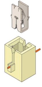
In IDC system, terminals are provided on a metal band. Manufacturers insert terminals into a plastic cavity by using automatic or semi-automatic insertion equipment. The plastic cavity must use glass-filled material to have mechanical stability and can be molded in the customer’s coil or can be part of a separate component. This molded cavity has two slots on the opposite sides and an inlet chamfer on each slot. The magnet wire coming from the coil is pre-positioned in these two slots manually or through a winding tool. The wire rests on a support or on an “anvil” in the cavity.
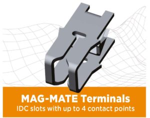
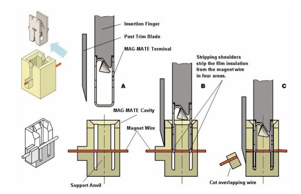
 The MAG-MATE terminal has two IDC slots with inlet chambers on the input points of slots. The terminal is positioned on the magnet wire in the plastic cavity and then inserted. Terminals “clean” the insulating film from the wire surface during the insertion. When the terminal has been definitively positioned, the wire is fixed between the two slots for the insulation displacement, to assure a safe and reliable termination. During this process, hermetically sealed contact points are created between the wire and the terminal. The opposite side walls of each slot of the terminal have a residual elastic energy that keeps the pressure constant on the wire, assuring a safe and reliable connection in the long term. Molded plastic slots fix the wire on each side of the metal terminal, assuring an anti-traction action.
Aluminum termination
The termination of the aluminum magnet wire use to represent a challenge for the IDC technology. Environmental and mechanical stresses cause in aluminum many more “creep” and “stress relaxation” phenomena than what with copper. Magnet wire manufacturers have succeeded in minimizing “creep” and “stress” phenomena.
The studies carried out by TE indicate that motor manufacturers can shift from copper wires to aluminum wires and use standard insulation displacement terminals to eliminate the pre-stripping and soldering that need specialized manpower.
To assure that the connection process leaves the wire in an optimal region of the connector slot, technicians must indicate the optimal insertion depth for the single application.
Compact recently patented connection
«Currently, – explained us Ugo Aime, Product Manager Appliance of TE Connectivity – the market trend is focused on developing products that can be used in applications where space is a premium and design-to-cost is extremely important. Reducing components and material, keeping performance, is paramount for success.
According to this strategy, we have developed a new proprietary concept with the support of of P.K. Senthil Kumar, Global Engineering Manager who works in our Bangalore branch, in India.
This concept relates to an assembly for electrical devices that demand a compact and automated solution to transfer power from a power source.
The assembly comprises a TE terminal with IDC that allows solderless magnet wire termination at the bottom and solderless PCB termination through press-fit on the top, with a tab connected with PCB using again press-fit termination».
- Large gas-tight contact zone
- High reliability due to stored energy
- Minimum damage to plated-through holes during application
- Especially suited for multi-layer PCBs
- More economic board manufacturing due to larger hole tolerances compared to the use of a solid pin Application can be made by the end-user
- High-end TE Connectivity application tooling available
- Extraction force equal to Pin/PCB min 40N
MAG-MATE Connector
- Terminates all magnet wire film insulations
- Eliminates need for pre-stripping conductors
- Eliminates need to solder/weld
- Excess magnet wire is automatically trimmed during the termination process
- Simultaneously terminates two magnet wires of the same size in one terminal (for splicing or bi-filing) Available in strip form for semi-automatic or fully automatic insertions
- High speed, fully-automated integrated systems provide uniform terminations reliability at the lowest possible applied cost
- Clean metal-to-metal interface produces stable, gas-tight electrical terminations free of oxides and other contaminants
This solution offers different advantages:
- Cost efficiency: when used with compliant pin variants, a compact solution is obtained that can be automated;
- BOM (Bill of Material) reduction: the connection can be completed with two parts only;
- Reliability: this solution needs minimal intervention and precisely controlled termination eliminates human error;
- Cleanness: it is environment friendly since eliminates need for pre-stripping and pre-solder/weld.
Moreover, «Customers can design their products without using wires and cables; we want to protect this solution of ours on a global scale» – specifies Aime.
Innovative semiconductors for electric mobility

The increase of OEM partnerships in the ambit of the electric vehicle production is the tangible proof of the market’s neat direction. News, on the other hand, unceasingly confirm several manufacturers’ conversion will towards a global electric offer.
Concerning this, one of the latest news regards the Swiss STMicroelectronics that has undertaken a collaboration in the e-mobility sector with Renault Group and the British Arrival developer. With Renault, the collaboration focus is the development, the production and the supply of STMicroelectronics products and associated packaging solutions for the power electronics of Renault Group’s electric vehicles. The brand target is reaching higher ranges, lower battery costs and improvements in recharge processes.
In its turn, STMicroelectronics is releasing components based on innovative materials like silicon carbide and gallium nitride: if silicon is replaced by silicon carbide in semiconductors, switching times decrease and the operation at higher temperatures is possible, too.
«ST is at the forefront of the development of advanced power semiconductors enabling the mobility industry to move to electrified platforms. With higher-efficiency products and solutions based on advanced materials such as Silicon Carbide and Gallium Nitride, we will support Renault Group’s strategy for its next generation of electric and hybrid platforms,” said Jean-Marc Chery, President and Chief Executive Officer, STMicroelectronics. “ST and Renault Group share a common vision for more sustainable mobility. This partnership will be another step forward in the progressive decarbonization process initiated by the mobility industry and its supply chain».
Stepper motors: typologies and technical features

Stepper motors play an important role in the manufacturing industry world. Their use prevailigly depends on expectations and applications. If we aim at high precisions, mechanical and electric sturdiness, user friendliness, control and maintenance of the rotor’s position also without power supply, then this motor typology is ideal.
In the present article, we are treating the main typologies of available stepper motors on the market, the essential structural aspects and their operation characteristics in static and dynamic conditions.
The stepper motor is used in small-power drives because it is less efficient than other motors. It allows achieving high positioning precisions and it is suitable for the sectors of robotics, automotive, 2D plotters, 3D printers and several other ambits.
Their name derives from the fact that a well precise angular rotation, precisely called step, is set at each control. They are piloted by opportune electronic switching circuits with open-loop position control. In absence of a specific control, the stepper motor maintains the position reached. In general, we can state that all stepper motors are composed by a stator, where are present the windings made up by copper wire coils, and by a rotor.
In the ambit of the manufacturing industry, stepper motors are classified as follows:
- Permanent magnets (PM);
- Variable reluctance (VR);
- Hybrid (HY).
Permanent magnet stepper motors
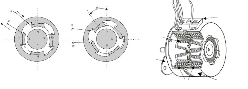
The rotor consists of a permanent magnet and shows, on its surface, the same number of poles as those present on the stator, where two phases (or windings) are present.
If we indicate with D the number of pole pairs and with α the pole angle, i.e. the angle taken up by a pair of NS (north-south) poles, we can express the following relation:
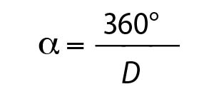
This type of motor can be excited in three ways:
- Single phase, where windings are powered individually and the rotor rotates at each step by 90° and the entire sequence corresponds to a complete revolution of the same;
- Two-phases, where windings are powered simultaneously, with the rotor that aligns between the two pole expansions (operation used when we want to have high torque);
- Half-step. The power supply, in this case, concerns first a phase and then both, successively only the second and so on. At each phase change, the rotation step is by 45°.
In Figure 1, we can see a schematization of the permanent magnet stepper motor.
Variable reluctance stepper motors
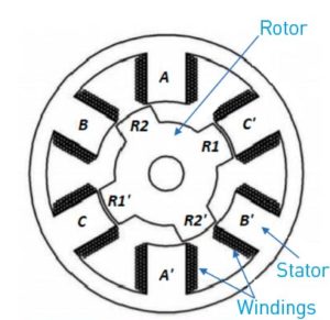
The operation principle of the variable reluctance stepper motor (Figure 2) can be ascribed to the tendency of mobile parts to be arranged in minimum reluctance conditions. This operation corresponds to attaining inductance and maximum flux. Reluctance, precisely, measures the opposition of a material to the transit of the magnetic flux. The VR motor has a grooved-iron rotor and a stator constituted by a stack of laminations with toothed poles. The rotor has a different number of teeth, or pole expansions, from stator’s. The latter features ns teeth, while the rotor body nr=ns±2. The angle among teeth (ϑr/s) is:
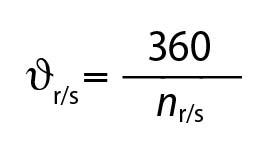
Where s and r stand, respectively, for stator and rotor.
Considering the stator, on each pair of opposite teeth is present a winding that constitutes a phase. The number of phases (F) is given by:
![]()
The minimum number of phases is three (A, B and C). It is not possible to make this motor typology run with two phases only, since the rotation sense would not be determined.
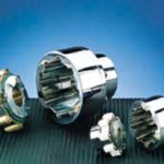
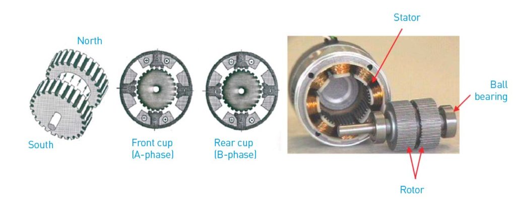
Hybrid stepper motors
The vast majority of stepper motors is hybrid (HY). They group the characteristics of PM and VR motors.
As shown in Figure 3, the rotor is composed by two parts, called cups, magnetized in axial sense (one North and one South), holding a series of teeth alternated to slots. Cups are fitted out of phase, so that the teeth of one correspond to the voids of the other. Indicating with α the angle among the rotor teeth, the phase displacement between the cups is α/2. The stator is similar to the one of VR, with a lamination stack with toothed poles but with just two phases. When the A-phase is excited, the S polarized teeth of the front cup are aligned with the teeth of the N-pole. In the rear cup, with teeth out-of-phase by α/2, the contrary occurs: the N polarized teeth of the rotor are aligned with the teeth of the S-pole of the A-phase. The misalignment between rotor teeth and B-phase ones is worth α/4. When the B-phase is excited, the rotor must rotate by α/4 to be correctly aligned with the poles of the B-phase.
In the successive steps, the front rear cup is always aligned with the N-pole of the excited phase while the rear cup is aligned with the S-pole of the same phase. After Z configurations, the rotor has moved by one tooth, therefore the number of steps per revolution (S) is:
S= nr∙Z
Torque developed in static conditions
Under static conditions, a stepper motor of whatever kind can develop the following torque:
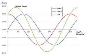
- Holding Torque. Let us consider a stepper motor of any type (PM, VR or HY) and let us power a single phase. The rotor will position itself in a determinate stable position. If, from the outside, we apply a torque and we impose a θ rotation, the magnetic attraction between stator poles and the rotor will oppose the external load, generating an equal opposite torque to the applied torque. Such torque is called holding torque (HT) and it is maximum when the rotation angle of the rotor is equal to α/4, where α is the pole angle, i.e. the angle taken up by a pair of poles. In such condition, rotor’s poles are in intermediate position with regard to the ones of the stator and are subjected to both the attraction of the opposite pole and to the repulsion of the homonymous pole. If we go on increasing the rotation, the stall torque starts diminishing, to the extent of being annulled by an angle equal to α/2. The homonymous poles of rotor and stator are aligned and repulsive forces have null tangential component and create no torque. Such condition corresponds to a situation of unstable balance as the torque is null but a small rotation (positive or negative) is sufficient to make the rotor return to the successive or previous step. The reaction torque, in fact, changes its sign and tends to make the rotor return to the initial position or to the position corresponding to the successive step. The situation illustrated in Figure 4 refers to a PM motor.
- Detent Torque. When a stepper motor is not powered, we would expect a null torque at the rotor. Actually, in PM or HY motors, even in absence of power to the stator phases, a Detent Torque DT appears. The entity of such torque ranges from 5% to 20% of the Holding Torque. In case the motor must maintain the position in absence of power supply, we try to rise the detent torque as much as possible with a suitable profile of teeth. If, instead, such torque is bothering, we will try to minimize it. It is worth noticing that the average value of the detent torque is not null, owing to the friction on bushes.
Torque developed in dynamic conditions
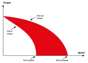
Operating the motor with some piloting circuits, it is possible to assess the operation of stepper motors in dynamic conditions. In technical literature, we can distinguish two operation typologies (Figure 5):
- Operation in pull-out (pull-out torque). The maximum torque the motor can develop during the rotation is called pull-out torque and it is equal to about 90% of the holding torque. In practice, we suggest choosing the size of the motor to work with torque corresponding to about 50% of the Holding Torque. At the so-called pull-out speed, the relative torque annuls. Catalogues, then, provide graphs of the Pull-out torque according to speed.
- Operation in pull-in (pull-in torque). To allow the motor to develop the Pull-out torque, it is necessary that the drive takes it to the wished speed, through opportune acceleration ramps. The frequency of impulses to single phases must gradually increase up to the desired frequency, if we want to develop the pull-out torque. However, drives are not always so sophisticated: in many applications, the still motor is immediately powered at the maximum frequency, without using gradual acceleration ramps. This is the operation in pull-in. If the speed is low, the motor starts in pull-in without difficulty but, at higher speeds than the so-called pull-in speed, the thing is no longer possible and the motor does not start even without load. In catalogues, manufacturers provide the torque curve in pull-in, too.
Conclusions
Stepper motors play an important role in the manufacturing industry world. Their use prevailingly depends on expectations and applications. If we aim at high precisions, mechanical and electric sturdiness, user friendliness, control and maintenance of the rotor’s position also without power supply, then this motor typology is ideal. However, we should take some limits into account, like the impossibility of having high speeds, the heat production and, especially, the need of providing for suitable piloting systems.
Custom-tailored materials for metal pretreatment and functional coating

As part of its active global support for the metal coil industry, Henkel is partnering with major coil producers to implement dedicated process solutions for end applications in e-mobility. In addition, the company is also addressing demands for reducing the complexity of downstream manufacturing steps by enabling continuous upstream functional coating processes without compromising the technical properties of the coated material.
Metal coil producers play an essential role in the market of hybrid and fully electrical vehicles, supplying steel and aluminium coils to the manufacturers of batteries, transformers, converters, wound cores, shunt reactors and other key components for e-drive and electrified powertrain systems.
Henkel’s process know-how extends across the entire value chain from the rolling oil for electrical steel to specific pickling inhibitors and cleaners to specialized new functional and conductive thin coatings, such as for covering the aluminium foil used in EV battery systems. Besides providing reliable corrosion protection for painted or unpainted substrates, these products have been custom-tailored to improve the overall performance of e-mobility applications by enhancing insulation and bonding properties, magnetic permeability and electrical conductivity.
Latest product innovations targeted at both upstream and downstream metal pretreatment and functional coating for end products in e-mobility include Bonderite O-TO dedicated product range and Bonderite M-CR 12 series. Bonderite is a registered trademark of Henkel and/or its affiliates in Germany and elsewhere.
Cylinders and suspensions: the choice of Ferrari Purosangue

TrueActive™ Spool Valve (TASV) technology by Multimatic comes into play by revolutionizing the role of shock absorbers, transforming a passive suspension into a completely active system.
Multimatic TASV shock absorber is pioneer to integrate a unique liquid cooled 48V three-phase brushless electric motor to deliver supplemental force through a bespoke twin-lead ball screw and gearbox assembly into the damper shaft and to the vehicle.
Each actuator group of the TASV shock absorber receives direct controls from a controller of the vehicle dynamics that constantly optimizes the vehicle’s performances and passengers’ drive comfort, far beyond what is possible with adaptive and semi-adaptive suspensions.
Alessandro Formenti, CEO at Vega Cylinders Company commented, complimenting on the choice of Ferrari Purosangue: “Imagine to drive your car without perceiving how you are moving. No longer feeling motor accelerations or pitching when cornering. It seems unbelievable, isn’t it? It seems a very distant choice from the sport driving. However it is the choice Ferrari made by installing some suspensions that annul drive sensations. These active suspensions have an electric 48V motor inside, connected with a special computer that reacts to the car’s stresses. Ferrari affirms this system helps fight load transfers and body movement, almost eliminating lateral body roll and shifting and distributing the load across the tyres. #Purosangue does not need anti-roll bars”.
A solution to power motor control

Through the completion of the distribution system for MSFS motor starters for automation boards, Eaton makes available for its customers a solution to power motor control and protection circuits enriched with numerous novelties, including a 125 A power supply module, new adapters for modular and box-type switches and a 5 A /24 VDC power supply.
The distribution system has been designed to offer a safe solution for the distribution inside the automation board and it is now equipped with a 125 A power supply module, hence the nominal capacity of the bus bars of the system itself. This allows using MSFS at its highest use current, permitting its full exploitation, while the previous limit was 80 A.
The system is positioned between the base solution, constituted by three-pole bus bar blocks, and the higher-level solution characterized by SASY60i distribution bus bar system, therefore defining a new intermediate standard in terms of cost, versatility and current values for automation systems.
Eaton, in the context of the widening of MSFS system, now proposes new adapters that extend the MSFS use also to utilities not strictly connected with the motor starter. This is possible because they allow connecting to the system both modular FAZ switches up to 63 A and the box-type NZM1 switch up to 125 A.
Meanwhile, in the suitable version (ROSF), also the new hybrid EMS2 starters (Electronic Motor Starter) can be coupled to the MSFS system.
Moreover, among the novelties the system completion provides for, there is also a three-phase 5 A /24 VDC power supply that, in most of automation applications, allows powering 24 VDC auxiliary circuits of the electric equipment of a machine without providing for further power supplies. Finally, the adapters offered until now for «PKZM0/PKE + soft-starter DS7» combinations extend their use possibility also to variable-speed DE1(1) starters up to 1.5 kW.
Wires for electric motors: a new standard for the coating

It is called Tau, it is a Turin start-up in electric mobility and advanced materials and it collected 6.75 million Euros of funding for its innovative wire for electric motors, with the target of developing and implementing state-of-the-art technologies starting from 2022, able to accelerate the transition to the Factory of the Future for e-mobility chain manufacturers.
The round involved a variety of international investors, including a consortium of two Middle-Eastern sovereign wealth funds, the Russian Direct Investment Fund (RDIF) and a German investment manager.
The start-up is specialized in wires and components for electric motors, with applications in the automotive, energy and agriculture sectors, and it has developed the DryCycle technology, which defines a new standard of wire coating. Through the strict use of solvent-free polymers, the solution eliminates the release of noxious VOC and greenhouse gases, whereas a simplified production process minimizes the use of resources, decreasing the energy consumption and wastes. LILIT technology by Tau provides the quality control to assure the reliability of the polymeric insulation in the magnetic wire and in electric steel.
The vision of Tau consists in doubling the power of electric motors in a determinate size and the funds of the recent capital increase will be used precisely to accelerate the development of new products, to enlarge the range of high-performance wires and to increase the industrial production, to provide global manufacturers of electrical cars, buses, trucks, aircrafts and ships starting from the beginning of 2022.