Friday, April 19, 2024

Hitachi enters the automotive world

To face the growing market of the sustainable mobility in the United States, the Japanese company Hitachi has decided entering the segment of electric motors for battery vehicles.

Last August 19th, for this purpose, they have established Hitachi Automotive Electric Motor Systems America, with Shingo Nakamura as President.

The location where electric motors will be produced is in Kentucky, exploiting already existing offices and factories in Berea city, covering almost 260,000 square metres.

Manufacturing is expected to start in 2022.


Acoustic monitoring and background noise in industrial environment

acoustic analysis

Since any interruption in the manufacturing process can cause a serious financial loss for the company, it is very important to prevent unplanned shutdowns of electric machinery. Hence, monitoring and diagnosing the health of electric motors is crucial, and continues receiving more and more attention. One of the possibilities for performing diagnostics of electric machines is by analysing sound emitted by object of interests. The quality of acoustic monitoring is very much dependent on the background noise of the environment in which the machine is operated. Some attempts to create condition-monitoring methods based on acoustic analysis were made in the past (Refs. 1-4).
Recently, acoustic analysis has attracted more and more attention, and has been applied in many fields – speech recognition, for example. However, condition-monitoring methods based on acoustic analysis are still considered difficult to implement in an industrial environment due to the background noise.
The easy availability today of data collectors and sensors as accelerometers or current probes drives the use of many condition-monitoring systems based on those measurements. However, it is still very often the case that site engineers are asking for inspection of the machine when they notice abnormal sound.
Instead of isolation of the sound and its analysis, a typical “solution” is to perform measurements of vibration, current, temperature or voltages that are not always indicative of the problem. Even though what was reported was abnormal sound, existing solutions are trying to detect the fault by various types of measurements, as opposed to showing that sound is emitted by a specific part in the first place. This, in turn, might limit the amount of possible diagnostic decisions, thus limiting the amount of required effort.
For this reason, in many cases the first diagnostic attempt is made by highly experienced engineers who are able to initially detect and diagnose the problem by simply listening for the sound source. For many years, diagnostics in the industry were performed “by ear,” with subsequent assessment of the emitted sound. Still, the influence of background noise can strongly affect the quality of such a judgment.
Today’s trends in the job market lead to a situation where there is less and less people who are experienced enough to judge the condition of an object by listening to the sound it makes. It is the result of the fact that many people prefer to do office work rather than working in an industrial environment. As is shown, in the Global Employment Trend document (Ref. 5), or in the list of the top 10 jobs forecast for next decade (Ref. 6), this situation will be even more prevalent in the future. However, there remains a necessity of doing the initial investigation of objects to localize the abnormal sound to perform immediate action.
A solution of the described problems might lie in the usage of acoustic analysis for objects-of-interest diagnostics. Thus far, it has been relatively difficult to create a reliable, acoustic-based condition monitoring system due to the fact that sound measurements are always affected by background noise. However, recent technologies like acoustic cameras are able to successfully localize specific sound components and thus remove the influence of such noise (Refs. 7–8).
A variety of faults that can occur in induction machines have been extensively studied and many monitoring methods have been proposed to detect problems (Ref. 9). Most of those methods for condition monitoring of electric motors utilized vibration or motor current signature analysis (MCSA) (Refs.9–11). While vibration and current signature analysis-based monitoring techniques are well known and well-accepted, acoustic measurements are not so popular in industrial application.
This paper describes a diagnostic method for induction motors based on acoustic measurements, while vibration analysis is used as a reference for assessment of the value of acoustic measurements.

Measurements Tools

Acoustic camera

The idea of the acoustic camera is to do sound source identification and quantification, and to create a picture of the acoustic environment through the processing of the multidimensional acoustic signals received via microphone array and to overlay that acoustic picture on the video picture (Ref. 7). Other possible acoustic camera applications include use as test equipment for non-destructive measurements for sound identification in vehicle interiors and exteriors (Refs. 7–8 and 12); trains and airplanes (Refs. 13–14); and for measurement in wind tunnels, etc. Additionally, some studies show the application of acoustic camera for unmanned underwater vehicles (Ref. 15), robots and robotized platforms, etc. It can also be used for passive acoustical sensing in battlefield environments (Ref.16). In this work, a 48-microphone acoustic camera was used for sound measurements; parameters for the microphones are presented in table 1.
acoustic analysisAcoustic holography technique was used for analysis of the sound source. Acoustic holography technique is a method that is used to estimate the sound field near a source by measuring acoustic parameters away from the source via microphone array. This is a well-known technique and its description can be found in (Refs. 16–17).

Vibration measurements

Vibration measurements are one of the most popular methods for condition monitoring of electric motors. Typically, piezoelectric accelerometers are used for measurements of the vibration. For the purpose of the present work, vibration measurements were taken as a reference for the sound measurements. Vibrations were collected with ABB’s MACHsense-P condition monitoring tool. MACHsense-P is a walk- around condition monitoring service tool provided by ABB that specifically focuses on electric motors. Vibration signals were measured using 4 simultaneous data capture channels and analysed for mechanical and electromagnetic defects. The frequency range used for analysis by MACHsense-P tool is from 0 Hz to 12,800 Hz. The vibration analysis presented in this paper is embedded functionality in the MACHsense-P tool.

Measurements analysis and comparison

All vibration and acoustic measurements where done in an industrial environment. Since induction motors are the most widely used machines in industry (Ref. 18), two of the same type three-phase induction motors were chosen. Nameplate details of the motors are presented in Table 2.
acoustic analysisBoth motors were located relatively close to each other, and both of them were driving centrifugal pumps of the same type through direct coupling. Both motors where operating at the same load level. Motor case 1 is considered healthy while motor case 2 is considered to have a combination of static eccentricity and soft foot. As soft foot typically results in static eccentricity, this combination of faults is very common.

Results based on vibration measurements

For both of the motor cases, vibration sensors were located horizon- tally on the center of the body of the motors. Figure 1A presents a vibration spectrum of the healthy motor case while Figure 1B presents a vibration spectrum of a combination of static eccentricity and soft foot motor case. Since static eccentricity can be typically visible in low-frequency range, both figures present frequencies from 0 Hz to 200 Hz. You may notice that Figure 1B contains a high peak – at around 100 Hz.
acoustic analysis
The value of this peak is above 0.12 gs, while in Figure 1A this peak is smaller than 0.02 gs. As presented in (Ref. 12), static eccentricity causes additional forces visible in vibration at frequency fecc – given by following equation:
fecc = 2 ∙ fline
Where fline is power supply frequency. In the above case, both motors were supplied by 50 Hz; therefore static eccentric-related frequency fecc is visible at 100 Hz. By taking the amplitude of fecc frequency as the static eccentricity indicator, it is clearly visible that the motor in case 2 reached a higher level of static eccentricity than the healthy motor from case 1. With the MACHsense-P the indicator of static eccentricity is calculated automatically.
acoustic analysis

Results based on acoustic measurements

For industrial applications, when performing measurements using a microphone, background noise can- not be avoided. The background noise can be filtered out by post-processing methods of the measured signals. This is possible due to the different nature of the measured sound. The background noise (including the  aerodynamic noise of the cooling device) is   usually  a broadband signal with a more or less constant spectrum (Ref. 1). On the contrary, the induction machine generates sound that is characterized by many pure tones – at least for the sound produced by electromagnetic origin. Reference 1presents a method where before operating the induction machine, a measurement of only the background noise is conducted. This spectrum of the measurements is later subtracted from the measured spectrum, with the induction machine in operation. However, this noise filtering approach is not accepted in industry because it affects the industrial process.
Reference 11 describes a method that isolates the frequencies related to the motor presented in electric current measurements. The same approach can be applied for vibration or acoustic signal. As presented in (Ref. 11), by knowing motor parameters and motor slip, all the frequencies related to motor condition can be identified. Likewise, all motor-related frequencies can be found and identified in the acoustic signal, even if the signal contains back- ground noise.
Figure 2 presents an acoustic spectrum of average signal via microphone array.
acoustic analysis
Figure 2A presents acoustic spectrum of a healthy motor case, while Figure 2B presents an acoustic spectrum of a combination of static eccentricity and soft foot motor case. Both figures are obtained for frequencies ranging from 0 Hz to 200 Hz. Similar to vibration cases, it is possible to notice that Figure 2B consists of a high peak at around 100 Hz, while Figure 2A does not. Value of this peak is above 600 mPa, while in Figure 2A this peak is smaller than 350 mPa. Those results are very similar to vibration-based results, and they are clearly indicating static eccentricity; however, in case of acoustic signal there is no assurance that this frequency emanates from the motor.
To solve this problem, the acoustic holography technique can be applied to find the sound source of the frequency of interest, in this case, 100 Hz.
acoustic analysis

Conclusions

In this paper, an acoustic-based technique for the condition monitoring of electric motors was presented. Vibration analysis was used as a reference for assessment of the value of acoustic measurements. Acoustic measurements were performed via 48-microphone acoustic camera. Two induction motor cases were examined a healthy motor case and a combination of static eccentricity with soft foot case. For fault case, respective frequencies were identified in both vibration and acoustic signal. Based on acoustic holography technique, the fault-related acoustic frequency source was localized in the center of the body of the faulty machine. As presented in the results section, one can say that acoustic signals can be successfully used for condition monitoring of electric motors in noisy industrial applications. Obviously, single acoustic signal is disturbed and noisy compared to vibration signals; therefore sound localization technique via acoustic camera was needed to solve this problem. An additional benefit of sound analysis is the fact that the acoustic sensors need not be attached directly to the motors, which is often difficult in industrial applications.
(Maciej Orman and Cajetan T. Pinto)

References
[1] Van Riesen D., Schlensok C., Henrotte F., Hameyer K.: “Acoustic measurement for detecting manufacturing faults in electrical machines”, 17th International Conference on Electrical Machines ICEM, (2006)
[2] Verma S. P.: “Noise and vibrations of electrical machines and drives; their production and means of reduction”, International Conference on Power Electronics, Drives and Energy Systems for Industrial Growth, Vol. 2, pp.1031, 1996
[3] Verma S. P., W. Li: “Measurement of vibrations and radiated acoustic noise of electrical machines“, Sixth International Conference on Electrical Machines and Systems ICEMS, Vol. 2 (2003), pp. 861
[4] Gaylard, A., Meyer, A., Landy, C., A. “Acoustic evaluation of faults in electrical machines “, Seventh International Conference on (Conf. Publ. No. 412), Durham, p. 147 -150
[5] Employment Trends unit of the ILO Employment Sector, “Global Employment Trends 2012: Preventing a deeper jobs crisis”, International Labor Office, Geneva, 2012.
[6] WorldWideLearn “Top ten jobs”, WorldWideLearn.com Copyright, Quinstreet Inc., 2012.
[7] Miljko M.Eric., 2011, Some Research Challenges of Acoustic Camera, 19th Telecommunications forum Telfor,Page(s):1036-1039
[8] Ulf Michel, “History of acoustic beamforming”, Berlin Beamforming Conference (BeBeC) 2006, 21-22. Nov.2006
[9] Tavner P.J., 2008, Review of condition monitoring of rotating electrical machines, IET Electrical Power Applications, Vol 2(4), Page(s): 215-247
[10]Orman M., Orkisz M., Pinto C. T., 2011, Slip Estimation of a Large Induction Machine Based on MCSA, Diagnostics for Electric Machines, Power Electronics & Drives (SDEMPED), IEEE International Symposium on, Bologna, pp. 568 – 572, 2011
[11]Orman M., Orkisz M., Pinto C. T., 2011, Parameter identification and slip estimation of induction machine, Elsevier, Mechanical Systems and Signal Processing, Vol 25, Page(s): 1408-1416
[12]S.Guidati, “Advanced beamforming techniques in vehicle acoustic”,Berlin Beamforming Conference (BeBeC) 2010.
[13]C.Cariou, O.Delvedier “Localizing aircraft noise sources with large scale acoutic antenna” 27th International congress of the aeronautical sciences
[14]J.S.Pascal, J.F.Li “Use of double layer beamforming antenna to identify and locate noise in cabins, EURONOISE, Finland, 2006
[15]Hans-Elias de Bree, Jelmer Wind, Erik Druyvesteyn, “Battlefield Acoustic”, Microflown ebook, chapter 21
[16]Korpel Adrianus, “Acoustic imaging and holography”, IEEE Spectrum, Volume: 5 Issue: 10, pp. 45 – 52, 1968.
[17]Mueller, R.K. “Acoustic holography”, Proceedings of the IEEE, Volume: 59 Issue: 9, 1971
[18]Long Wu, “Separating Load Torque Oscillation and Rotor Faults in Stator Current Based-Induction Motor Condition Monitoring”, Georgia Institute of Technology, 2007.
[19]M.Mijic, D.Masovic, D.sumarac Pavlovic and M. Adnadevic, “A Model of Planar Microphone Array Realized with Low-cost Multimedia Microphones”, Telecommunications Forum (TELFOR), pp. 1040 – 1043, 2011.

Ford project that studies the electric motors of the future

In Germany, Ford with other partners has created a consortium to develop next-generation electric motors, to study new production processes.
The research project is called HaPiPro 2 and its target is developing new base products and processes that will play a protagonist role in the mass-production of components for electric vehicles, exploiting flexible, scalable and efficient methods.
The name HaPiPro 2 refers to the pin technology used in the wire winding inside electric motor groups: the Hairpin technology is a key innovation area in electric drive systems and the research will study precisely how to exploit its potential to allow the efficient manufacturing of several electric motor variants on a single production line.
The consortium includes, besides Ford, Thyssenkrupp System Engineering, Rwth and Engiro departments of 3D printing and product engineering of the University of Aachen, and electric motor experts.
The new research centre will be hosted inside Ford factory in Koln -Niehl, in Germany, “a unique advanced engineering platform for all companies, to research and to assess the future of electric motor manufacturing processes», as Gunnar Herrmann, executive President of Ford in Germany, described.

Audi, powertrain with three electric motors

Audi’s will of further strengthening its electric expansion has led to the development of the S versions of Audi e-tron and Audi e-tron Sportback, which adopt three electric motors, two at the rear axle, able to supply an overall maximum power of 503 HP. It is an absolute premiere for mass-produced models.
The electric four-wheel drive avails itself of the innovative electric torque vectoring function with active variable distribution of the torque on the rear axle. Reactivity, performance and feeling while driving reach a new dimension.
503 HP and 973 Nm of torque allow shifting from 0 to 100 km/h in 4.5 seconds.

Non-conventional design of concentrated windings

Fig. 1b

Thanks to appropriate numerical optimisation techniques, it is possible to drastically reduce the losses that originate in permanent magnets due to eddy currents, with a small reduction in the torque that can be developed by the machine. In the same way, it is possible to design machines with concentrated windings with combinations of number of slots and poles traditionally considered incompatible or not feasible in symmetrical form. This is confirmed by the studies carried out by Professor Alberto Tessarolo, University of Trieste, and by examples of how this approach can be of great application interest.

by Gianandrea Mazzola in collaboration with Professor Alberto Tessarolo,
University of Trieste

Professor Alberto Tessarolo, Trieste University

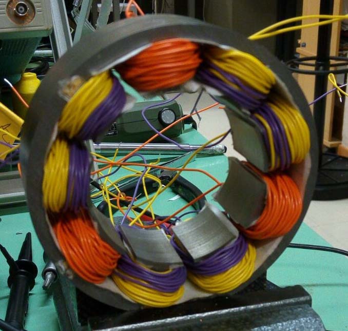
In the construction technology of modern electrical machines, the use of so-called “concentrated” or “wound tooth” stator windings is becoming more and more frequent, replacing, where possible, the more traditional “distributed” windings. The difference between the two types of windings can be appreciated by the examples shown in figure 1. It will be observed that the distributed winding consists of “ample” coils which embrace a relatively large portion and connect leads arranged in “distant” slots (figure 1a). Conversely, concentrated windings consist of “tooth coils”, i.e. coils each wound around a tooth in the stator’s magnetic core (figure 1b and figure 1c).

A drawback of concentrated windings is the fact that they, even when supplied with ideal currents, produce harmonic fields at the machine air gap which are capable of inducing losses due to eddy currents in permanent magnets and consequent overheating.
Moreover, it is not always possible to opt for concentrated windings. This is possible, in fact, at the state of the art, only for motors and permanent magnet generators in which the number of slots, indicated by Z, is similar (a little higher or a little lower) to the number of poles P.

In general, concentrated windings are usually considered feasible only if the number of slots Z and the number of poles P satisfy a precise algebraic relationship. More precisely, for the feasibility of winding, the quantity K, as shown in the following relation:

must be an integer number, having indicated by MCD (Z, P/2) the Maximum Common Divisor between Z and P/2. The above relation restricts the choice of the number of slots Z and poles P to a limited number of combinations (which we can define as “conventional combinations”). The limitation in question becomes particularly restrictive in the case of windings with more than three phases (m>3), as is often required to increase reliability. In the case of multi-phase windings, the scope of permissible poly-slot combinations is significantly reduced, thus significantly limiting the designer’s choice and precluding, in some cases, the adoption of wound tooth technology.

Large reduction of losses in the magnets, with small reduction in torque

In response to these critical issues, Professor Tessarolo has recently developed and proposed a methodology for the optimized design of concentrated windings, using multi-layer configurations.
“Configurations in which – explains Professor Tessarolo – there can be several coils of different phases wound around the same tooth, as exemplified in figure 2, identifiable by different colours depending on the phase to which they belong.
The methodology, which is based on a particular algorithm of quadratic optimization, nevertheless easily implemented in widespread computing environments (such as Matlab), permits reducing some of the drawbacks of concentrated winding machines.
“In particular – observes Professor Tessarolo – this methodology makes it possible to reduce the risk of overheating of the magnets due to harmonic fields at the air gap and the problem of the limited number of combinations of project-acceptable poly-slots, especially in the case of a number of phases greater than 3.
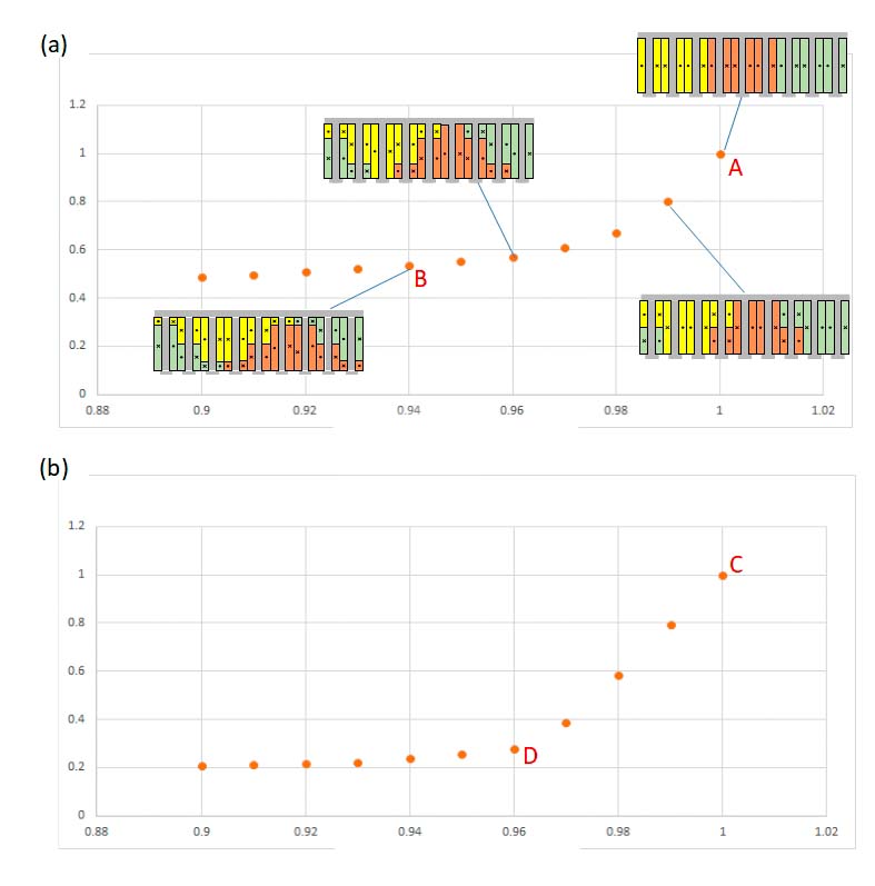
With regard to the reduction of ohmic losses in magnets, a multi-layer configuration optimized for wound tooth winding makes it possible to reduce the losses in magnets by up to 50%, at the price of a relatively limited reduction in the power developed by the machine. The potential for design optimization is exemplified in figure 3 for the combinations of 9 slots-8 poles and 12 slots-10 poles. The torque and losses of the magnets are normalized with respect to the value they assume for the traditional configuration (with a single coil for each tooth), represented by points A and C. Each point represents an optimized multi-layer design configuration.

“For example, in configuration B for the 9/8 machine, losses are reduced by about 50% at the expense of a 6% reduction in the nominal torque,” says Professor Tessarolo. “In the D configuration for the 12/10 machine, the losses in the magnets can be reduced by about 70% at the price of a drop of only 4% in the nominal torque.”

The optimization also extends the field of acceptable poly-slot combinations

The proposed optimisation method also permits extending the range of possible poly-slot combinations.
“In other words – underlines Professor Tessarolo – the method provides a symmetrical multi-layer configuration for a concentrated winding with a generic number of Z slots and P poles, even if Z and P are not such as to give a whole K in the above-mentioned equation”.
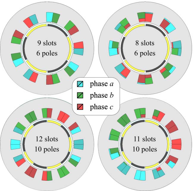
For example, figure 4 shows the cross-section of an 8-slot, 6-pole (unconventional) machine compared to the conventional 9-slot, 6-pole machine; similarly, the cross-section of an 11-slot, 10-pole (unconventional) machine is compared to the conventional 12-slot, 10-pole machine.

Fig. 2 Example of multi-layer concentrated winding. The coils wound around the teeth are distinguished by different colours depending on the phase to which they belong
Fig. 3 Magnetic losses and developable torque of machines with (a) 9 slots and 8 poles; (b) 12 slots and 10 poles, designed in optimized multi-layer configuration

“From the comparison between conventional and non-conventional configurations – says Professor Tessarolo – it appears that the latter, in the face of a greater construction complication, in some cases show better performance. For example, the 9-slot and 6-pole machine in figure 4 has a high torque ripple which is about double that of the 8-slot and 6-pole machine. Or, to quote another example, the 11-slot and 10-pole machine has permanent-magnet losses around half those of the 12-slot and 10-pole machine”.

Fig. 4 Cross section of an 8-slot and 6-pole (unconventional) machine compared with the conventional 9-slot and 6-pole machine; similarly, the cross section of an 11-slot and 10-pole (unconventional) machine is compared with the conventional 12-slot and 10-pole machine

To give a more complete idea, the tables in figure 5 show a comparison between conventional (white cells) and non-conventional (grey cells) configurations in terms of winding factor and specific losses produced in the permanent magnets. It can be observed that some unconventional configurations have interesting and competitive values.

Fig. 5 Winding factors and specific losses in permanent magnets for machines with different combinations of slots and poles. Grey background cells represent unconventional configurations

Operating benefits also for multi-phase machines

The possibility of using unconventional configurations can be particularly useful when designing multi-phase machines or machines consisting of several three-phase windings. This circumstance often occurs in applications that require continuity of service even in the event of a fault.
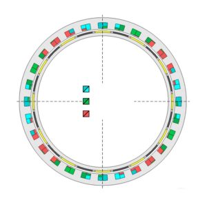
“For example – comments Professor Tessarolo – if you wanted to build a 12-phase machine, or with double three-phase winding, with eight poles, the conventional rules available in literature would force you to choose, to obtain a whole K from the above-mentioned report, a minimum number of 24 slots. It is clear that, for small machines, the use of Z equal to 24 could lead to unacceptable slot dimensions. The use of an optimized and unconventional multi-layer configuration can, in this case, be of help, making it possible to create a three-phase 8-pole, 9-slot double triad machine, as shown in figure 2”.
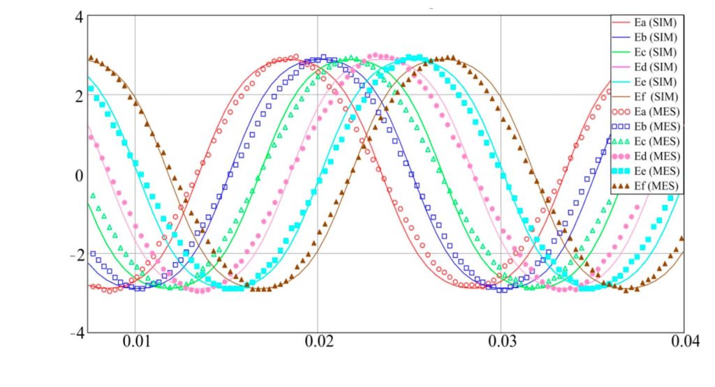
The prototype of this machine was also tested, recording the vacuum induced electromotive forces and then verifying the perfect electrical symmetry of the 9-phase winding, as shown in figure 6.

Fig. 6 Vacuum electromotive forces in a simulation machine (continuous stroke) and in a measuring machine (dotted traces) for 12-phase machines with unconventional concentrated winding with 9 slots and 8 poles
Fig. 7 Cross section of 12-phase motor consisting of 4 non-conventional concentrated windings with 7 slots and 6 poles

A further example of application is the 12-phase motor shown in figure 7, consisting of four three-phase windings offset by 90 degrees, each characterized by 7 slots and 6 poles. The choice of an unconventional winding in the case of what is shown in figure 7, was dictated by the need to have (for the maximum frequency allowed and the nominal speed) a total number of 24 poles, to be divided between the 4 independent units, of which the machine must consist for fault tolerance reasons. This resulted, for each unit, in a maximum number of 6 poles.

“The choice of 2 and 4 poles – underlines Professor Tessaroli – was not possible, as it led to excessive stator and rotor yoke thicknesses, such as to exceed the design dimensional constraints imposed on the radial dimensions. In this case, the project concerned the development of an electric outboard motor with integrated propeller, where space constraints were predominant. The number of poles for each unit was therefore fixed at 6, the choice of the number of slots such as to give an acceptable winding factor was between Z=9, Z=8 and Z=5, as shown in figure 5”.

The first (conventional) one was rejected because the torque ripple was too high. The only remaining options were therefore unconventional, i.e. 8 slots and 6 poles or 7 slots and 6 poles. The second was chosen because of its lower magnet losses and the almost zero torque ripple.
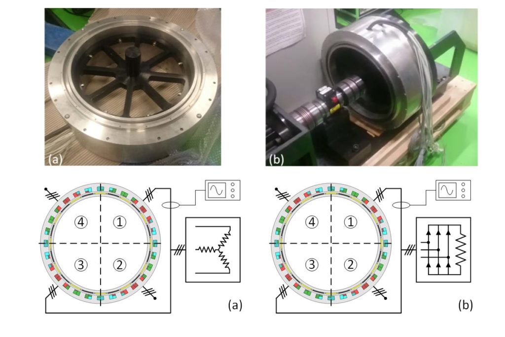
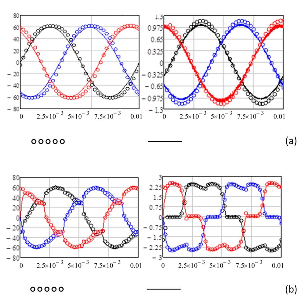
A prototype of the 7×4 slot and 6×4 pole three-phase quadruple winding machine was made (figure 8 a-b) and this was tested by connecting in parallel 2 of the 4 stator units and loading them respectively on a resistor star and on a diode rectifier bridge (figure 8 c-d). The results of the tests are shown in figure 9, where the waveforms recorded on the test bench are compared with those obtained by simulation of the machine with the finite element method in the time domain.

Fig. 8 Prototype made (a) and its installation on a test bench. Test configurations with two winding units placed in parallel and loaded (a) on star resistors and (b) on diode rectifier
Fig. 9 Voltage and current waveforms, from measurement and simulation to finite elements, of the machine working from a generator loaded on (a) resistor star and (b) rectifier bridge

The results confirm the perfect symmetry of the machine and the excellent agreement between design forecasts and experimental behaviour. Similar waveforms, which do not show any unexpected phenomenon as a consequence of the choice of an unconventional winding, were also obtained by loading the other two machine units.
Professor Tessarolo concludes: “It can be said that the realization of concentrated electric windings, beyond traditional shapes and the classical limitations assumed for your project, have wide margins of optimization and extension. Provided that they are implemented on a multi-layer basis”.

It has been shown in these pages how, with appropriate numerical optimization techniques and the operating methodology proposed by Professor Tessarolo, it is possible to drastically reduce (even by more than 50%) the losses that originate in the permanent magnets due to eddy currents, with a small reduction in the torque which the machine is able to develop. It was also shown that, through similar optimization techniques, it is possible to design machines with concentrated windings with combinations of number of slots and poles traditionally considered incompatible or not feasible in symmetrical form. Finally, some application examples have been illustrated of how this can be of interest, especially (but not only) in the design of concentrated winding machines with more than three phases. It is therefore an operational approach and a methodology that, in fact, provides useful elements for greater freedom in design and execution.

“Baby electric motors”, strollers with e-stroller system

Nine parents out of ten pay attention to strollers’ comfort and safety and, concerning this, Bosch has ideated a new system that marks its entry in a new market.
In the wind tunnel, with 7-degree intensity according to Beaufort scale, the air hits the stroller at a speed of 60 km/h and strongly shakes the canopy, but the stroller does not move thanks to the new e-stroller system by Bosch. It is much more than an electric traction, it is a stroller assistant with a complete range of comfort and safety functions. Besides the thrust support and the automated braking function, this system is in fact provided with an alarm function, with a series of highly technological sensors and the possibility of connecting it to the smartphone through an app.
The traction system includes two silent electric motors on the rear axle, a Bluetooth module and a system of smart sensors. These sensors, used also in smartphones, measure also the stroller’s speed and acceleration, detecting also the type of surface travelled.

Electric Motors Efficiency needs better copper

A new manufacturing process yields highest conductivity copper composites at bulk scale. This is a discovery of researchers at Pacific Northwest National Laboratory (PNNL): they have increased the conductivity of copper wire by about five percent. Higher conductivity means that less copper is needed for the same efficiency, which can reduce the weight and volume of various components that are expected to power our future electric vehicles.

The laboratory teamed with General Motors to test out the souped-up copper wire for use in vehicle motor components. As part of a cost-shared research project, the team validated the increased conductivity and found that it also has higher ductility-the ability to stretch farther before it breaks. In other physical properties, it behaved just like regular copper so it can be welded and subjected to other mechanical stresses with no degradation of performance. This means that no specialized manufacturing methods are necessary to assemble motors-only the new advanced PNNL copper composite.

The technology can apply to any industry that uses copper to move electrical energy, including power transmission, electronics, wireless chargers, electric motors, generators, under-sea cables, and batteries.

General Motors Research and Development engineers verified the higher conductivity copper wire can be welded, brazed, and formed in exactly the same way as conventional copper wire. This indicates seamless integration with existing motor manufacturing processes.

«To further lightweight motors, advances in materials is the new paradigm – said Darrell Herling of PNNL’s Energy Processes and Materials Division. Higher conductivity copper could be a disruptive approach to lightweighting and/or increasing efficiency for any electric motor or wireless vehicle charging sytem».

Heft project for a new recyclable electric motor

Heft is the name of a European research that will be accomplished by the half of 2026, with the participation of Alma Mater Studiorum of University of Bologna and the Spanish University Mondragon Unibertsitatea. The target is developing a new motor for electric cars. Researchers are working at new synchronous permanent-magnet drive system able to assure lower costs, better efficiency and higher power, reducing the use of rare earths by even 50-60%.
The project, in fact, complies with Erma (European Raw Materials Alliance) goal, which intends to reduce the Old Continent’s external dependence on the front of the provisioning of rare earths, with at least 20% internal support to the demand within 2030.
Among the other targets, also the strengthening of the circular economy, with a new fully recyclable model, able to create development on the territory, meanwhile improving the green all-round approach. The European Union pursued the Heft project, allocating 4 million Euros in its favour, in the ambit of Horizon 2020, instrument of funding to the scientific research and innovation by the European Commission. The project started on December 1st 2022 and will go on for 42 months.
The specialists involved in the project are facing a series of innovative challenges concerning its configuration, focusing efforts on SiC inverters and on materials. For the validation of these high-efficiency low-cost innovations two successful electric cars will be taken as benchmark: Fiat 500e and Volkswagen ID.3.

Saietta: axial flux electric motor to electrify the world mobility

It is headquartered in the United Kingdom and it develops in pioneering way solutions for the automotive electrification and it is particularly in turmoil precisely for the great boom that the segment of electric vehicles is living, also due to the legislator’s contribution. We are speaking of Saietta, in search of new 250 collaborators and that has recently released its latest project: axial flux electric motor design, which combines both distributed windings with a yokeless stator.
Besides, the moment is particularly favourable: it has won a research contract through the Advanced Propulsion Center (APC) of the United Kingdom, but the witness by the chief executive officer of Saietta Group, Wicher Kist, a bit slows down enthusiasms: «We are ready for the future of transportation by stepping in with modern, lightweight electric motors as traditional internal combustion engines fuelled by petrol and diesel reach the end of the road. If the 2030 target is to be met, key decisions on future investment will need to be made quickly so companies like ours realize our full potential. That means more funding from UK government and quickly».
The company aims at a modular approach to its motors that are at the service of a broad range of vehicles, from scooters to trucks. Its first offer of commercial motors, for instance, AFT140, is optimized for the use of medium-size bikes and vehicles for last-mile deliveries, currently much more important solutions in terms of volumes in Asian markets rather than in Western ones. Precisely in this scenario, Saietta has recently announced a remarkable partnership agreement with Padmini VNA, one of the main automotive players in India.
The commercial agreement provides for Padmini collaboration with Saietta to develop new opportunities in the Indian market and renowned Indian two-wheel OEM players stand out among its customers, such as Hero MotorCorp, TVS, Bajaj Auto and Royal Enfield.

Turin, a new R&D Centre for electric and electronic components

MTA, multinational that operates in the global automotive sector through the two Electric and Electronic divisions, has announced the establishment of a new Research & Development Centre in Turin, in Mirafiori area, automotive excellence pole. The new centre, already in operation, will employ at steady-state about 25 engineers dedicated to the development of electric and electronic components, with a particular focus on products such as OBC (On Board Charger) and DC/DC converters intended for hybrid and electric vehicles, automotive, truck and heavy-duty applications. The new centre will host also a laboratory with test benches and forefront equipment to allow the autonomous execution of tests on power electronics components developed here.
“We intend, as it already happens with Milan Polytechnics, to establish a relationship of fruitful know-how exchange with Turin Polytechnics, an excellence for the whole automotive world. Therefore, the centre will allow us to support vehicle manufacturers even better, with an increasingly articulated and technologically advanced offer for new-mobility requirements”, stated Antonio Falchetti, Executive Director of MTA.