
In the Engineering Department of Palermo University, RPLab – Rapid Prototyping Laboratory is the laboratory where they design and implement prototypes of electronic power converters, control, conditioning and interface boards for research ambits in automotive, industrial and net-connected fields. Its interior hosts forefront LPKF Laser & Electronics machines. Managers have recently published a video that shows how is created an interface screen for an electric drive control based on a multi-level inverter and a permanent magnet brushless motor.
A showcase that accompanies the proposal of visiting the laboratory, which opens its doors to all to show its excellence and which is at the service of the Rapid Prototyping Laboratory graduation course.
The RPLab laboratory opens the doors

Sicilian students transform a car into electric

The first electric car, fully implemented by students and professors of the Technological Institute Verona Trento of the city was presented by Messina Commune. An old Renault 5 was taken from an abandoned and vandalized wreck and became an electrical jewel thanks to the use of recycled material. The old internal combustion engine was replaced by a DC electric motor directly coupled with the car’s original transmission, maintaining the kinematics. Renewable photovoltaic and wind power sources, as well as innovative batteries, are used: a sophisticated storage system with lithium anode and lithium iron phosphate cathode (LiFePO4), supplied by CNR ITAE to be tested on the vehicle in urban driving regime.
The initiative is framed in the ambit of MEME project – Electric Mobility for Ecosustainable Messina. “Innovation and environment protection. This is represented by this vehicle implemented for the first time in Italy by a scholastic citizen reality. We wish that this initiative may be the first of a long series of projects aimed at promoting an ecologic culture in cities”, declared the major Federico Basile.
“A project that has allowed joining professors’ experience with students’ creativity and enthusiasm, demonstrating how the collaboration among different generations can lead to surprising results. The electric car manufactured represents a concrete solution to decrease the environmental impact and the dependence on fossil fuels, and proves how the school can be a place of education and of innovation for a more sustainable future, besides concretizing in life experiences to be followed for future generations”, the comment by Superintendent Vadalà.
The innovative Wcs wind generator

It is worth saying: a wind of news is coming for the renewables of the future.
The Norwegian start-up Wind Catching Systems, established in 2017, has in fact designed an offshore wind turbine with an innovative floating wind power technology at competitive prices, which will make its debut in 2026.
The visual impact is impressive: the Windcatcher grid, a giant vertical net, over 324-metre high, whose meshes are hundreds of mini-wind turbines connected one another, arranged on a floating platform moored on the ocean floor.
The target is revolutionizing the technology for the offshore wind catching, a system competitive enough to operate without incentives, maximizing the energy production.
According to Wcs start-up, only one of these wind turbines might offer the double of the area exploited by the biggest standard wind turbines in the world and the smaller rotors can work much better even with wind speeds included between 40 and 43 km/h (27 mph). The overall effect, Wcs affirms, is the 500% rise of the yearly energy production.
Actually, each of these plants might replace five big single-turbine plants.
Wcs affirms these plants are ready for a service life of 50 years, compared to 30 years of a single large turbine.
Speaking of economic aspects, the plant is expected to supply offshore wind energy with the same cost as grid energy. In Norway, the average is currently about 86 Euros per megawatt hour and for their debut, in approximately 5 years, the price might even be around 80 Euros.
A super electric motor incoming

Winding-free, featuring excellent performances, low weight and volume. Here are the main features of the new motor at which is working the Emilia company Poggipolini, top player in titanium fasteners for Formula Uno and aerospace. The new motor will address aerospace and defence, but also the world of the electric traction for Motor Sport and high-end cars.
Concerning this, a key role will be played by the factory of the future “Speed Up Lab”, headquartered in the new factory at San Lazzaro di Savena, in an area of over 20,000 sq. m., close to the Manufacturing Center of Excellence inaugurated in 2019. Its mission is working in open innovation.
Recently, the company has established a partnership with Puglia startup Roboze to design and to manufacture the mechanical parts of electric motors, 3D printed with innovative materials such as Carbon Peek, a carbon-reinforced polymer. The collaboration will aim at accelerating the adoption of this new process technology, shifting from engineering to industrialization.
The technology of the new electric motors will be fully innovative and will precisely concern its operation, as well as materials, which will assure lower weight and simplification of architectures and manufacturing processes.
Measuring the efficiency of induction motors: what is the actual scenario?

The EU Regulation requires the measurement of efficiency for induction motors, as the surveillance task demanded to the different EU countries. Toward this goal, induction motors’ manufacturers and surveillance authorities should consider various issues related to measurement aspects, as the instrumentation to be adopted and the expression of measurement uncertainty.
by Edoardo Fiorucci, Dept. Industrial and Information Engineering and Economics, University of L’Aquila – Italy
The efficiency measurement is a critical issue in the induction motors market that concerns electric motors manufacturers, suppliers, consumers, and market surveillance authorities.
International Standards and Regulations
In 2009, the European Commission published the Regulation EC 640/2009) [1] concerning requirements for the eco-compatible design of electric motors.
This Regulation applies to single speed, three-phase 50 Hz or 50/60 Hz, squirrel cage induction motor, with 2, 4, and 6 poles, rated voltage up to 1 000 V, rated output power between 0,75 kW and 375 kW, continuous duty operation.
This Regulation does not apply to motors designed to operate wholly immersed in a liquid or integrated into a product (gear, pump, fan, or compressor), brake motors, and motors specifically designed to operate in particular environmental conditions.
This Regulation requires the measurement of efficiency for induction motors, as the surveillance task demanded to the different EU countries.
Toward this goal, induction motors’ manufacturers and surveillance authorities should consider various issues related to measurement aspects, as the instrumentation to be adopted and the expression of measurement uncertainty.
If we take a comprehensive look at the measurement procedures and at some basics of the measurement theory, we need to untangle ourselves among standard uncertainty, combined uncertainty, extended uncertainty, indirect and direct efficiency, and separation of losses tolerances of rated values.
Moreover, the standards seem to be not coordinated, so the operators can be in trouble if they aim at evaluating the efficiency with the related uncertainty, as required.
Two first remarks concerning [1] shall be made about uncertainty and tolerance.
In Annex II, the measurement uncertainty is considered, but only from a qualitative point of view: “…For the purposes of compliance and verification of compliance with the requirements of this Regulation, measurements and calculations shall be made using a reliable, accurate and reproducible method, which takes into account the generally recognised state-of-the-art methods, and whose results are deemed to be of low uncertainty, including methods set out in documents the reference numbers of which have been published for that purpose in the Official Journal of the European Union…”
The difference between the output mechanical power and the input electrical power is due to losses occurring in the motor. The determination of total losses shall be carried out by one of the following methods: measurement of total losses, or determination of separate losses for summation.
Tolerances for manufacturers are introduced in Annex III: “The authorities of the Member State shall test one single unit. The model shall be considered to comply with the provisions set out in this Regulation, if in the nominal motor efficiency (η), the losses (1-η) do not vary from the values set out in Annex I by more than 15 % on power range 0,75-150 kW and 10 % on power range > 150-375 kW…”
Although the effort in regulating the efficiency measurements, from an operative point of view, no numerical goals for the uncertainty are given, resulting in the issues we will discuss at the end of this paper.
The IE efficiency levels in [1] are in the IEC 60034-30-1:2014 Rotating electrical machines – Part 30-1: Efficiency classes of line operated AC motors (IE code) [2]. This standard establishes a set of limit efficiency values based on frequency, number of poles and motor power.
Let us consider the combined effects of [1] and [2], on the reference values for the efficiency, in a real scenario.
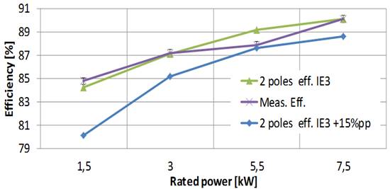
In Fig. 1, the IEC 60034-30-1 efficiency curves for 2-poles induction motors are depicted, for IE1, IE2 and IE3. The effect of the tolerances in [1] leads to the situation in Fig. 2a, with the effects of +/-(15/10) % uncertainty in power losses.
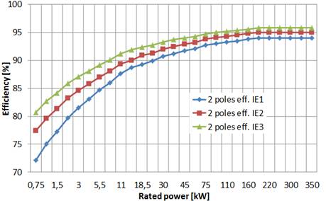
Each curve in Fig.1 should be replaced by a set of two curves, obtained by considering respectively 15 % (induction motors rated power up to and including 150 kW) and 10% (induction motors for rated power induction motors rated power above 150 kW) decrement and increment of the losses related to the IE efficiencies defined by IEC 60034-30-1, according to the rated power.
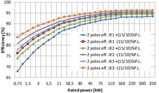
The obtained six curves are in Fig. 2a and Fig.2b. As a first remark, there are some overlaps because the IE2+(15/10)% curve is lower than IE1-(15/10)%curve, and the IE3+(15/10)%curve is lower than IE2-(15/10)% curve.
This issue could involve some difficulties in classifying an induction motor.
For example, the IE1 and IE2 efficiencies required for 5.5 kW 2 poles induction motors are 84.7% and 87%, respectively; the ranges depicted in Fig.2a are 82.40-86.99 for IE1 and 85.05-88.95 for IE2.
Let’s consider a rated efficiency of 86% declared by the manufacturer.
The considered motor can be simultaneously classified as IE1, because its efficiency is lower than % 86.99, but it can also be rated as IE2 because its efficiency is higher than 85.05%.
A similar problem can be raised for the overlaps of IE2 and IE3 curves. In Fig.2b the obtained curves for the higher rated power range are presented, as an expansion of Fig.2a.
Unfortunately, we have not considered the measurement uncertainty, yet.
Is it mandatory for the operators to evaluate the measurement uncertainty if they are measuring and then guaranteeing the rated efficiency of an induction motor?
Regarding the measurement laboratories, the general requirements for the competence, impartiality, and coherent operation of the laboratories are defined in the ISO / IEC 17025: 2017 [3] standard, which applies to all organizations that carry out laboratory activities but also to regulatory authorities and accreditation bodies.
It states that “testing laboratories shall have and shall apply procedures for estimating the uncertainty of measurement”.
So, we must refer to the uncertainty definition in the Guide ISO/IEC 99:2007, International vocabulary of metrology [4] as the “non-negative parameter characterizing the dispersion of the quantity values being attributed to a measurand, based on the information used.”
Coherently, the measurement result is a “set of quantity values being attributed to a measurand together with any other available relevant information”.
It is probably the most critical and neglected aspect in many experimental procedures in all the technical fields; each measurement result must be expressed as a set of data, not as a single point according to the Euclidean geometry.
Because of the impossibility of having zero uncertainty, we must define our results as a data set, whose width we tend to reduce according to the considered application, desired level of knowledge, budget, and available instrumentation.
In this scenario, the JCGM 100:2008 Evaluation of measurement data — Guide to the expression of uncertainty in measurement [5] is fully applicable because it establishes general rules for evaluating and expressing uncertainty in measurement intended to be applicable to a broad spectrum of measurement procedures.
All the above-mentioned recommendations and standards are to be considered together with the IEC 60034-2-1:2014 Rotating electrical machines – Part 2-1: Standard methods for determining losses and efficiency from tests (excluding machines for traction vehicles) [6]; it defines operatively the procedure for the measurement of efficiency.
The test methods are now grouped into preferred methods and methods for field or routine tests.
The preferred methods are presented as methods that allow low uncertainty; for a specific rating and type of machine, only one preferred method is currently defined.
The requirements related to the instrumentation are detailed and refined. Furthermore, the description of all the tests required for each method is explained, in the same sequence needed for the execution of the test itself, with flow diagrams that graphically show the sequence of tests.
As a general remark, it must be noticed an effort to model the effects of many experimental parameters in the evaluation of the different typologies of losses.
Some Experimental Results
In our Laboratory of Electrical Engineering at the University of L’Aquila, we have been testing several induction motors whose rated power is up to 15 kW (400 V, 50 Hz, TEFC, squirrel-cage), both for research and industrial applications since 1994 (Fig. 3).
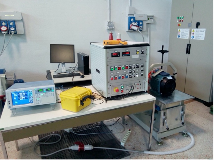
Today, our Laboratory is equipped with state-of-the-art instrumentation.
In detail, in this paper, some results about efficiency measurement according to the current version of the standards [5, 6] are presented.
Fig. 4 shows the experimental testing results for IE3 – 2 poles induction motors; the accuracy achieved in efficiency measurement is ± 0,30 % by adopting high accuracy power analyzers and mechanical transducers.
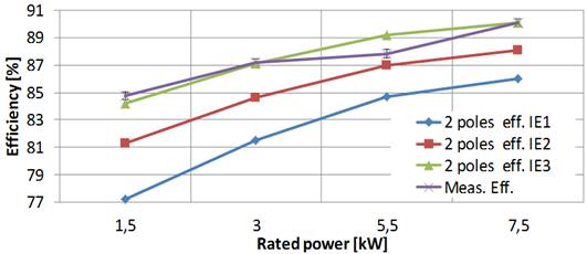
We can observe that only the 5.5 kW motor is below the IE3 efficiency; however, because of the allowed 15% uncertainty in power losses measurement, the manufacturer could correctly classify it as IE3 as suggested by Fig. 5.
This issue is more evident in Fig.6 for the 4-poles induction motors we tested; all of them are characterized by measured efficiency lower than the IE3 curve, which we have measured with experimental uncertainty of +/-0,40%.
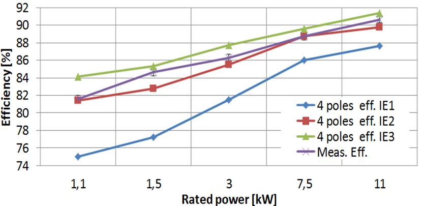
Nevertheless, although all of them are below the IE3 curve, they can be classified as IE3 because the manufacturer can take advantage of the allowed 15% uncertainty (Fig.7).

In other words, even if with a high accuracy measurement of efficiency, we demonstrate that an induction motor is below a rated IE efficiency value, the manufacturer could not be criticized because the EC Regulation N. 640/2009, Annex III allows him to perform the efficiency measurement with low accuracy.
Final Remarks and Conclusion
Finally, some remarks about legal issues can be raised in assigning an efficiency class for a measured efficiency.
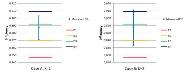
In Fig.8, what is the correct IE class, for a measured efficiency for the case A in which a coverage factor k=2 (95% confidence) is adopted according to the GUM [5]? The motor complies with IE2 requirements because all the data set is over IE2 level.
But I cannot exclude that it is IE3. If we extend the uncertainty, with k=3, (99% confidence), the data set covers 4 IE levels. So, which is the correct IE code for this motor?
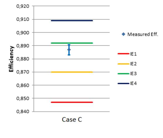
Maybe some additional suggestion of requirements in the international standards can be helpful, starting from the observation that the differences between two contiguous IE levels cannot be thinner than the measurement uncertainty; the desirable scenario is in Fig. 9.
Finally, how are two different data set to be considered if they are different? It is a typical situation in the measurement field. In this case, we must check if they are superimposable.
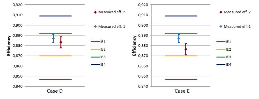
In Fig. 10, case D shows two sets that are compatible because they are partially superimposable.
Case E in Fig. 10 depicts how the measurements are not compatible, even if they lead to the same IE results because the motor complies IE2 level.
Some references that can be of interest to operators involved in this complex scenario are listed as [8-11].
References
[1] COMMISSION REGULATION (EC) No 640/2009 of 22 July 2009 implementing Directive 2005/32/EC of the European Parliament and of the Council with regard to eco-design requirements for electric motors.
[2] IEC 60034-30-1:2014 Rotating electrical machines – Part 30-1: Efficiency classes of line operated AC motors (IE code).
[3] ISO/IEC GUIDE 99:2007 International vocabulary of metrology — Basic and general concepts and associated terms (VIM).
[4] ISO/IEC 17025:2017 General requirements for the competence of testing and calibration laboratories.
[5] SO/IEC Guide 98-3:2008 (JCGM/WG1/100) Uncertainty of measurement — Part 3: Guide to the expression of uncertainty in measurement (GUM:1995).
[6] IEC 60034-2-1:2014 Rotating electrical machines – Part 2-1: Standard methods for determining losses and efficiency from tests (excluding machines for traction vehicles).
[7] Power Analyzer Accuracy and Basic Uncertainty Calculator R511.xls, 2021, [online] Available: http://tmi.yokogawa.com/.
[8] Rajan, A., Kuang, Y.C., Ooi, M.P.-L., Demidenko, S.N. Measurement uncertainty evaluation: Could it help to improve engineering design? (2019) IEEE Instrumentation and Measurement Magazine, 22 (2), art. no. 8674631, pp. 27-32. DOI: 10.1109/MIM.2019.8674631.
[9] G. Bucci, F. Ciancetta, E. Fiorucci and A. Ometto, “Uncertainty Issues in Direct and Indirect Efficiency Determination for Three-Phase Induction Motors: Remarks About the IEC 60034-2-1 Standard,” in IEEE Transactions on Instrumentation and Measurement, vol. 65, no. 12, pp. 2701-2716, Dec. 2016. DOI: 10.1109/TIM.2016.2599459.
[10] Dubois, C., Leblond, L., Pou, J.-M., Ferrero, A. Covariance evaluation by means of uncertainty assessment (2016) IEEE Instrumentation and Measurement Magazine, 19 (6), art. no. 7777646, pp. 12-18. DOI: 10.1109/MIM.2016.7777646.
[11] Bucci, G., Ciancetta, F., Fiorucci, E., Mari, S., Segreto, M.A. The measurement of additional losses in induction motors: Discussion about the actually achievable uncertainty (2019) Energies, 13 (1), art. no. 78. DOI: 10.3390/en13010078.
Man can fly. Here is the wingsuit with electric motor

The first test of a revolutionary wingsuit, which allows man “to fly” has been recently held in Austria. How? Thanks to a 15 kW electric motor that powers two 7.5 kW 25,000 rpm turbines.
The wingsuit, which allows flying at 300 km/h, is called Electrified Wingsuit and it is the fruit of a project funded by Bmw, whose protagonist is the designer Peter Salzman.
The test took place along the Alpine chain Die drei Brüder, where the man in the wingsuit jumped from a helicopter at three thousand metres of altitude.
At present, it is just a prototype, will it really be a possibility for all in the future?
Artificial intelligence for the creation of electric motors

An engineer from DNCL Technologies publicly talks about this hot topic, presenting the last novelties by the Indian company. DNCL Technologies provides Embedded Product Design and development company, DNCL offers Engineering Product Design Services and Industrial Design, Custom Electronics Product Design, IoT product Development PCB Design, Software Design included firmware and software programming services and RTOS services. «We started using an Artificial intelligence design service, and we are thrilled about the potential impacts of AI’s fusion with electric motors. We know that electric motors are a crucial part of many industrial and commercial applications and their efficient operation is essential to maintaining productivity and reducing costs. By implementing anomaly detection, condition monitoring, and predictive maintenance strategies, businesses can ensure that their motors remain in optimal condition, reducing the risk of downtime and costly repairs and extending the lifespan of their equipment».
About anomaly detection, «AI is our motor whisperer, picking up on those subtle cues we may miss. Abnormal vibrations, temperature spikes, unusual power consumption—all signs of underlying problems that left unchecked, could lead to severe damage or motor failure. Condition Monitoring is the round-the-clock guardian, keeping a watchful eye on key performance indicators like temperature, vibration, and power consumption. Machine learning models can detect those slight shifts in motor behaviour, hinting at potential issues».
Predictive Maintenance takes condition monitoring up a notch. By using advanced analytics and machine learning algorithms, AI can predict when maintenance will be needed. Imagine sensors installed in the motor system, collecting data on parameters such as vibration, temperature, current, pressure, and magnetic fields. This data is then processed and analysed to identify anomalies or patterns that could flag potential issues. Finally, by comparing historical motor performance data with real-time sensor readings, predictive maintenance systems can detect anomalies and predict when critical components may fail.
“Baby electric motors”, strollers with e-stroller system

Nine parents out of ten pay attention to strollers’ comfort and safety and, concerning this, Bosch has ideated a new system that marks its entry in a new market.
In the wind tunnel, with 7-degree intensity according to Beaufort scale, the air hits the stroller at a speed of 60 km/h and strongly shakes the canopy, but the stroller does not move thanks to the new e-stroller system by Bosch. It is much more than an electric traction, it is a stroller assistant with a complete range of comfort and safety functions. Besides the thrust support and the automated braking function, this system is in fact provided with an alarm function, with a series of highly technological sensors and the possibility of connecting it to the smartphone through an app.
The traction system includes two silent electric motors on the rear axle, a Bluetooth module and a system of smart sensors. These sensors, used also in smartphones, measure also the stroller’s speed and acceleration, detecting also the type of surface travelled.
Here is the study to extract magnets from electronic waste

The prestigious Bentley Motors brand aims at more sustainable electric motors and, concerning this, it has announced a specific triennial technological study. It is called RaRE (Rare-earth Recycling for E-machines) and will be based on the work accomplished by the University of Birmingham in the ideation of a method to extract magnets from electronic wastes. The goal is reusing the magnetic material extracted to implement new recyclable magnets to be integrated inside tailored auxiliary motors. Even more sustainability will be assured by the fact that the motors tailor-made through this method allow minimizing the complexity of some manufacturing phases, meanwhile supporting the development of the supply chain of the United Kingdom for both mass-production components and for small batches.
“While we are speeding up the electrification race, offering only hybrid or electric vehicles within 2026 and full electric within 2030, it is important to focus on each aspect of the vehicle sustainability, including sustainable provisioning methods of materials and components. RaRE promises a radical change of the electric recyclability, providing a source of low-voltage motors really tailored for a series of different applications and we are confident that results will provide a support for completely sustainable electric drives “. This is the witness by Matthias Rabe, member of the Board of Directors of Bentley Motors.
Ambitious electric motor goal from USA

QM Power and the SPARK Lab at University of Kentucky shared the combined results of a large-scale, multi-objective design optimization study, and lab testing of a prototype motor designed to meet the ambitious 2025 power density goals set by the US Department of Energy (DOE). The research demonstrated the high torque and speed capability of QM Power’s innovative permanent magnet motor technology. This, combined with advanced manufacturing and cooling technologies, achieved a record-high 50kW/liter volumetric power density for traction applications such as electric vehicles (EV).
The computational study was conducted at the SPARK Lab and an open frame lab prototype was designed and manufactured by QM Power. Tests and extensive simulations were conducted at University of North Carolina, Charlotte and at University of Kentucky to reveal the best outcome given trade-offs among efficiency, power density and power factor while achieving the DOE 2025 target. In 2019 the US DOE established the 2025 goal as part of an ongoing effort to reduce dependency on resources such as fossil fuels and rare earth magnets. It represents an ambitious 89% reduction in motor volume compared to 2020 targets. This project is among the programs which the DOE’s Vehicle Technologies Office deems to “have the potential to support radical new vehicle architectures by dramatic volume/space reductions and increased durability and reliability.”